Browse Author

beyerch

Technology expert, voider of warranties, mad scientist.

Tesla Reverse Engineering: MCU Teardown

Overview

When reverse engineering an important, and rather fun, step is disassembly. Digging into the internals of hardware & software typically provides many clues as to how you can exploit a system. If you know what technologies are being utilized, this will make it easier to understand how the product works and how to exploit it. Additionally, by knowing what key components / technologies are in use will give you a starting point for finding attack vectors. (E.g. known vulnerabilities) Additionally, in many cases, an analysis of the hardware will result in the discovery of diagnostic/debug access to the system. This is especially true for the Tesla Media Control Unit (MCU)

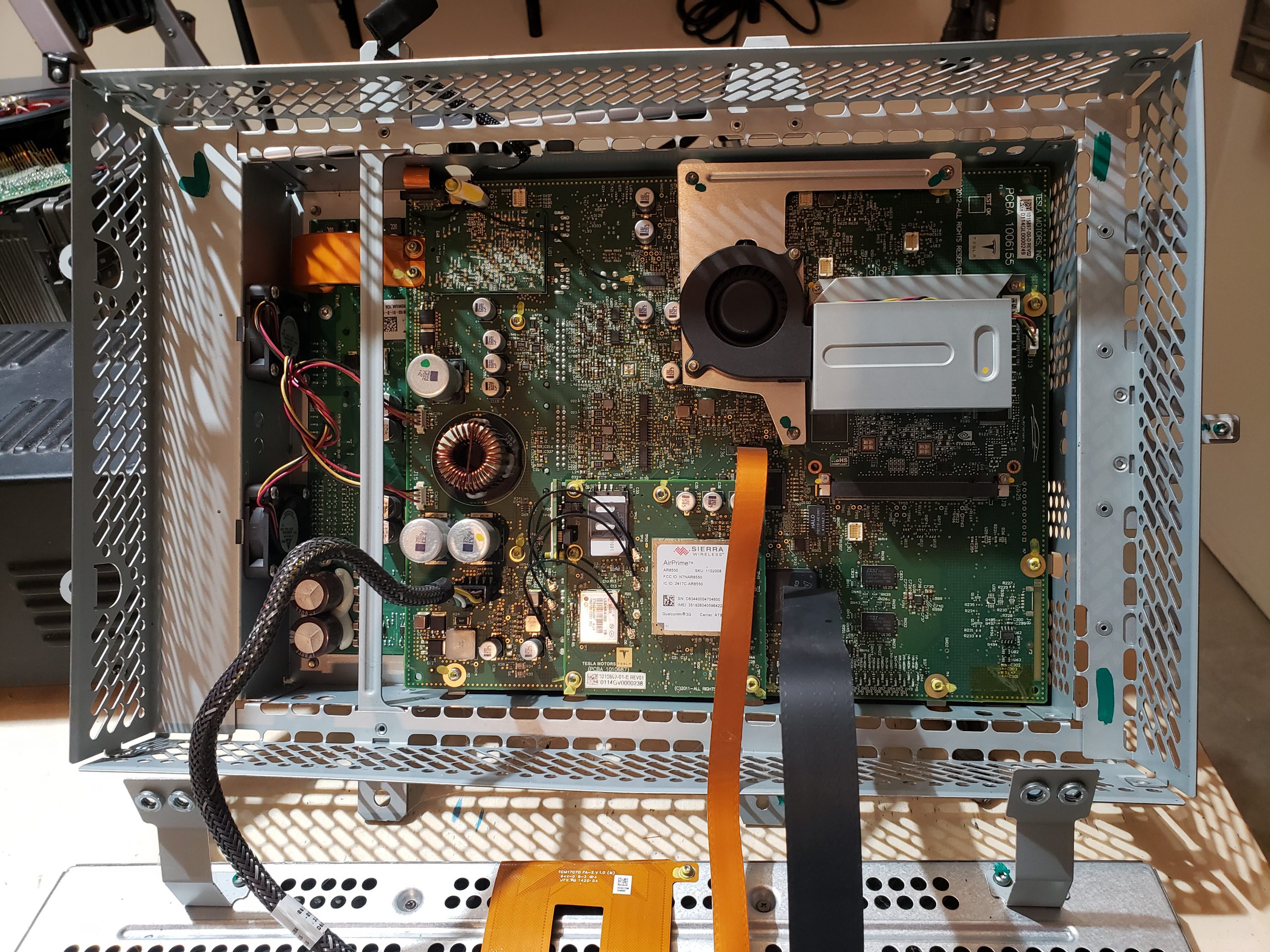
The MCU, which has numerous implementations, is a complex device which is critical to the operation of the Tesla vehicle. The MCU serves as the primary user interface for vehicle control/configuration, navigation, radio, entertainment, communication & coordination w/ other vehicle modules, diagnostics, and remote communication w/ Tesla HQ. Given the complexity of this unit, any/all clues to its operation will be extremely helpful in understanding how it operates. A full tear down & inventory of key components is ONE method to increase our knowledge.

The MCU consists of the key sub-assemblies:

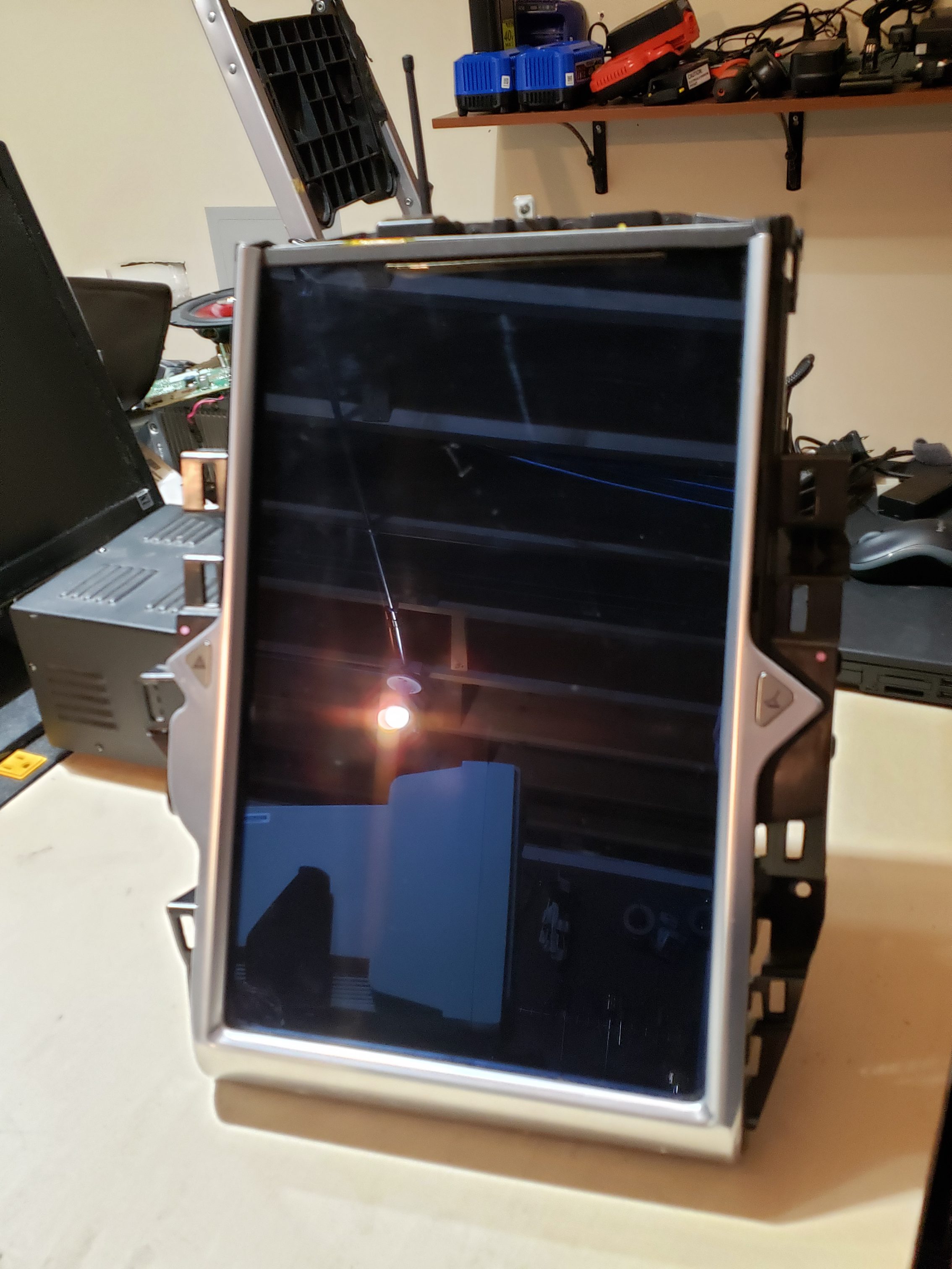
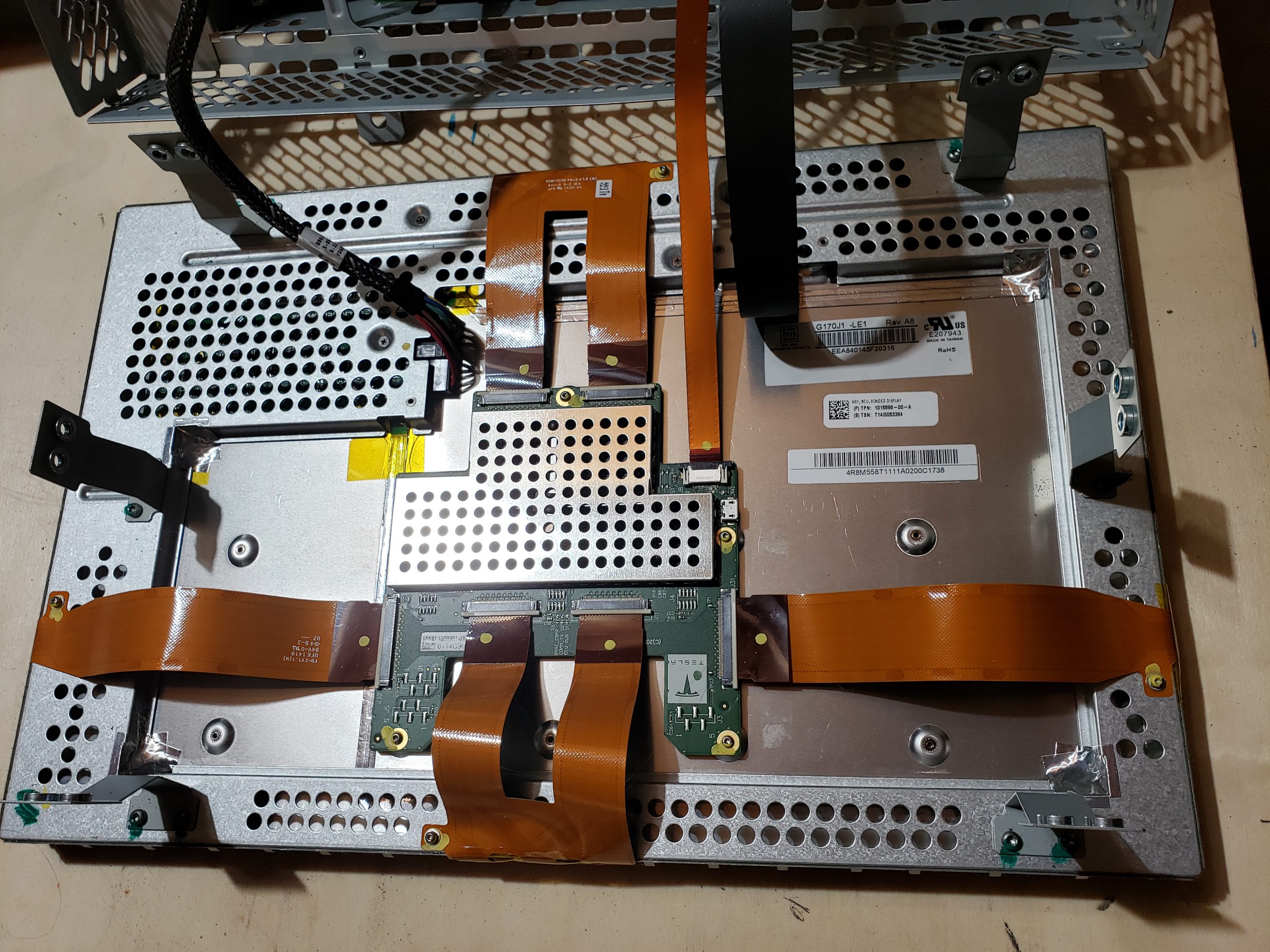
  • Bonded Display – For most people, this is the only assembly that matters as it collects user input and provides visual feedback.
  • Amplifier Assembly – Audio amplifier module which drives speakers, etc.
  • Cellular Communications – This sub-assembly is responsible for cellular communications. Early MCUs supported 3G while newer sub-assemblies support 4G/5G.
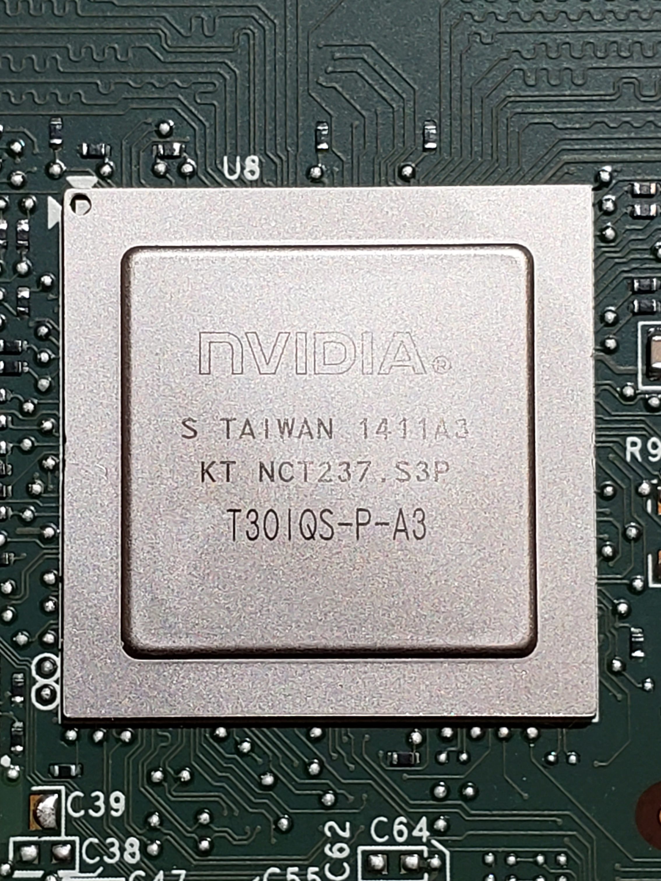
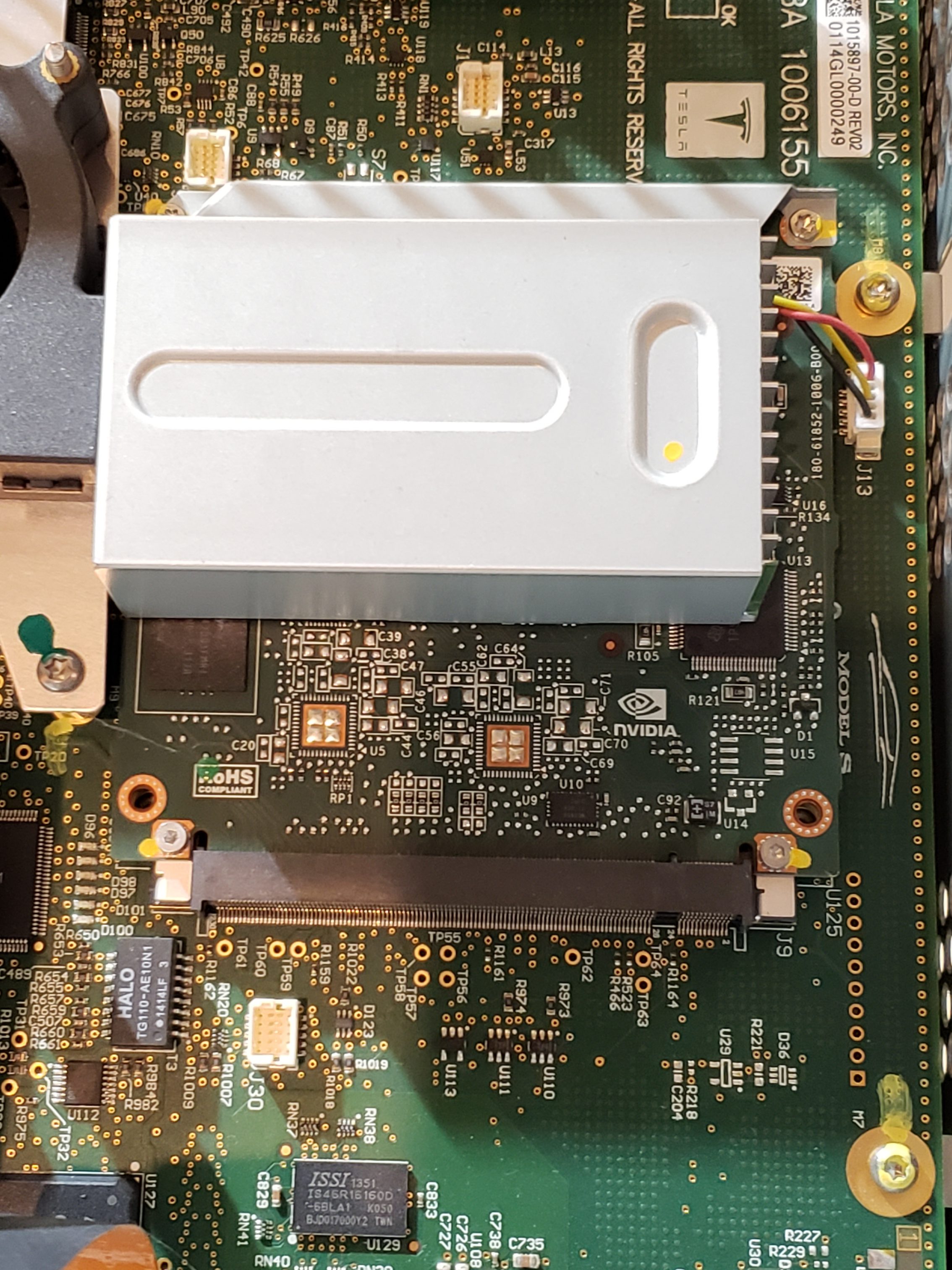
  • Infotainment Processor – This sub-assembly provides the main processing power for the MCU. For the MCU 1, this is powered by NVidia while MCU 2 utilizes Intel Atom, and MCU 3 contains an AMD Ryzen processor.
  • Main Board – This is the largest assembly and serves as the hub for all of the other sub-assemblies.

Bonded Display

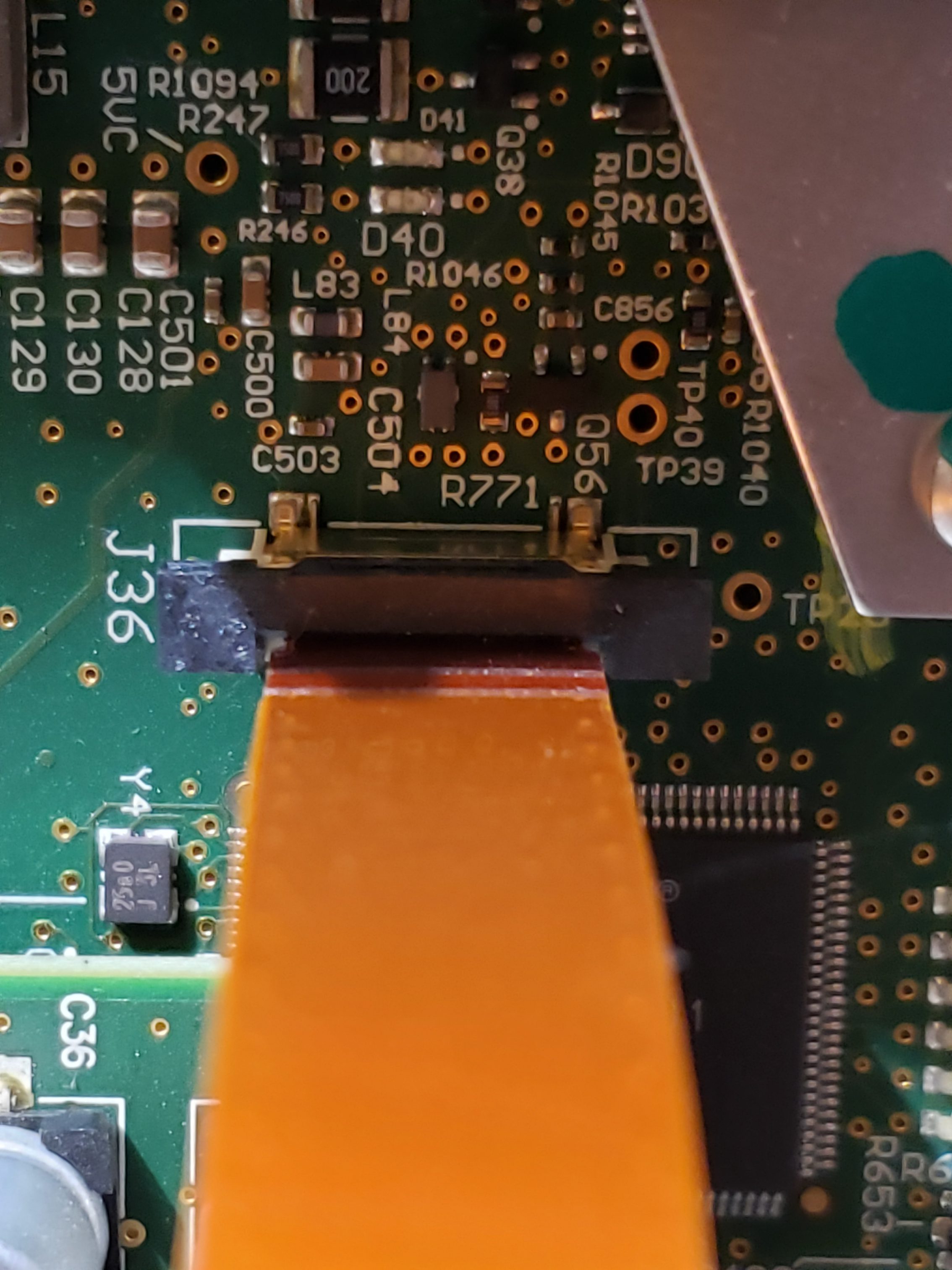
From a reverse engineering perspective, this is probably the least interesting sub-assembly. The electronics are relatively minimal and single purposed. I don’t expect there to be much value in focusing on this assembly. With that said, there is a USB port on the control board. I suspect this is probably used for pushing firmware in the factory.

Amplifier Assembly

Similar to the display, this assembly is also very single purposed and I don’t see any obvious value in focusing too much time here. A quick review of the circuit board does not find anything remarkably useful for reverse engineering purposes.

Cellular Communications

This module is far more interesting as it is responsible for remote communication, which is quite valuable. There are multiple prominently displayed components on this board of note. Additionally, you’ll see that this contains a removable SIM card. As the older modules came with “unlimited data”, perhaps you can repurpose this? ☺ It would additionally be curious to see if any data is on this card.

Infotainment Processor

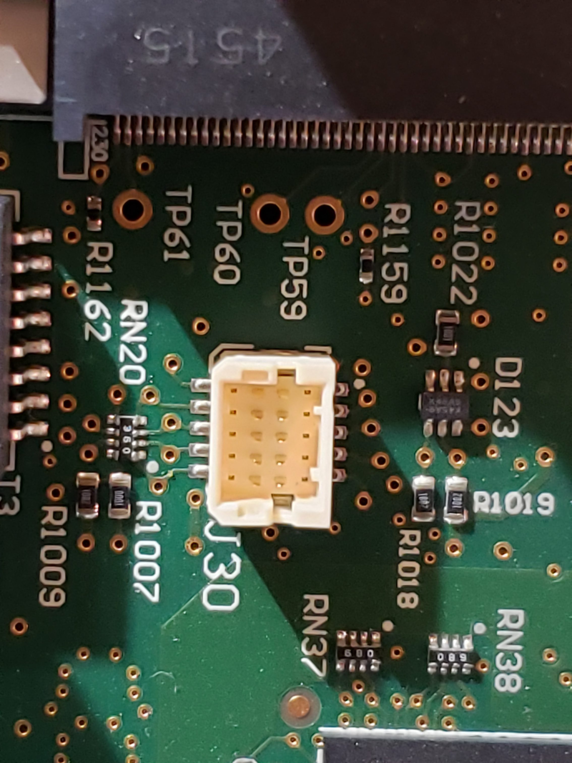
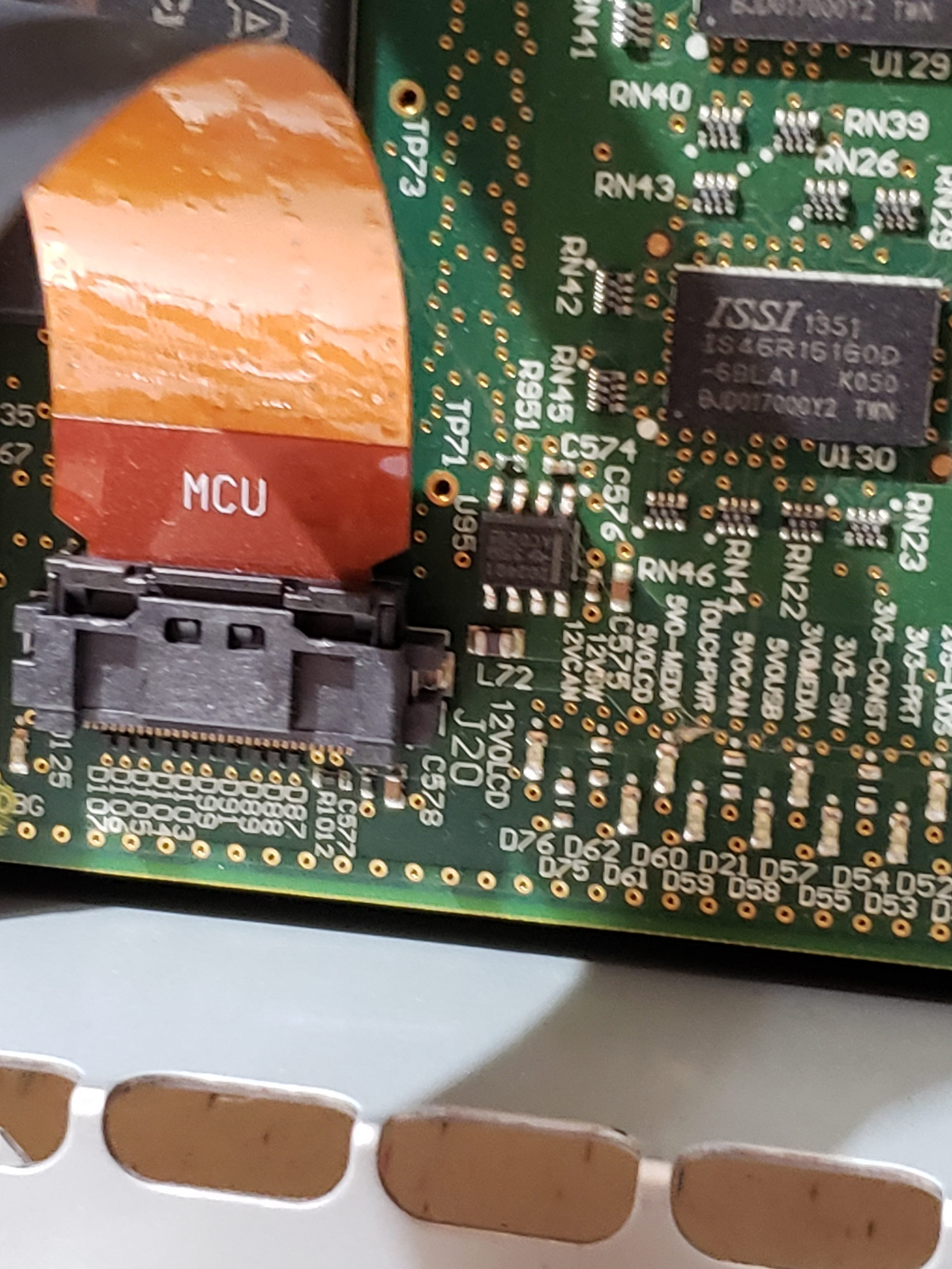
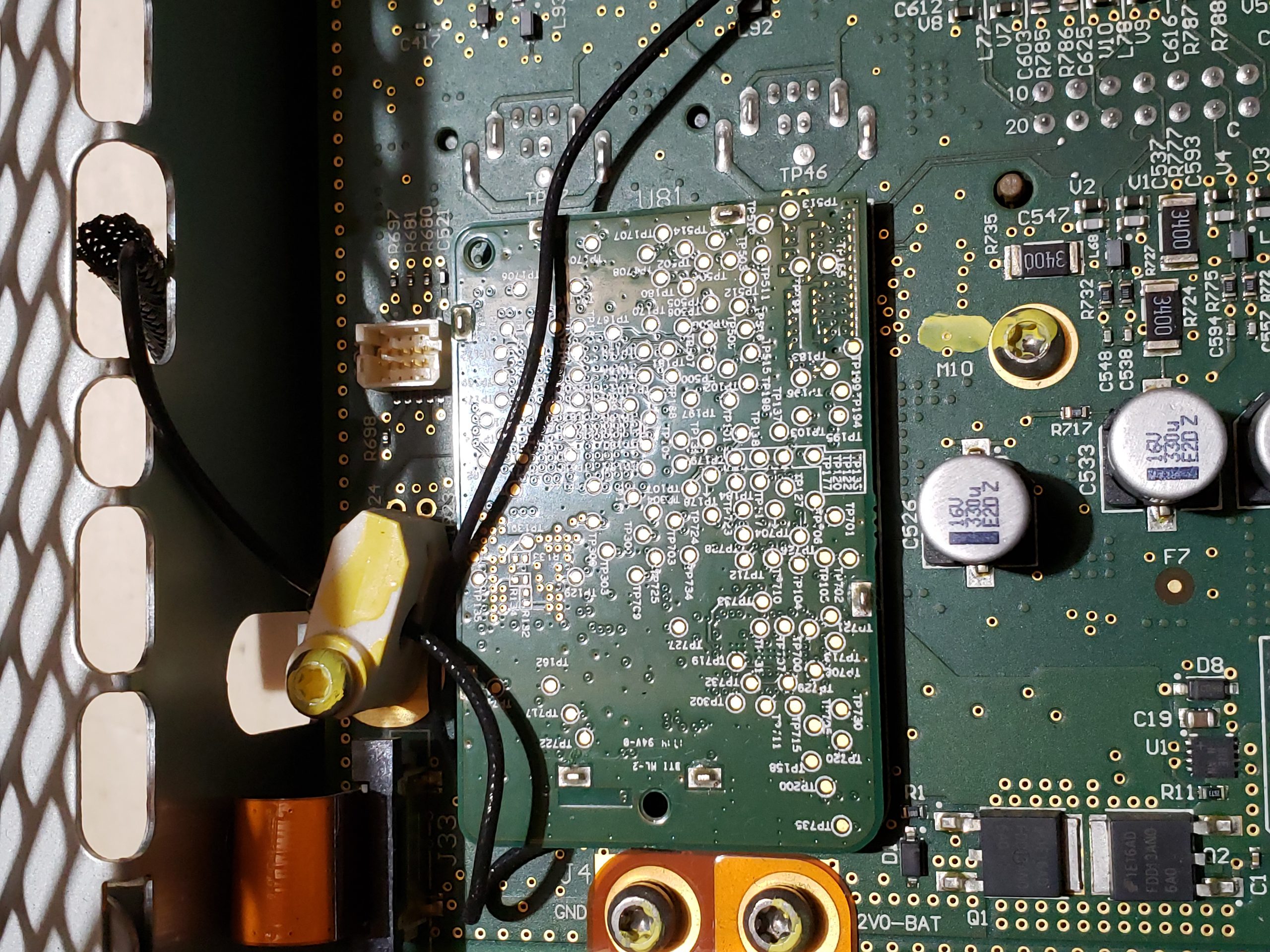
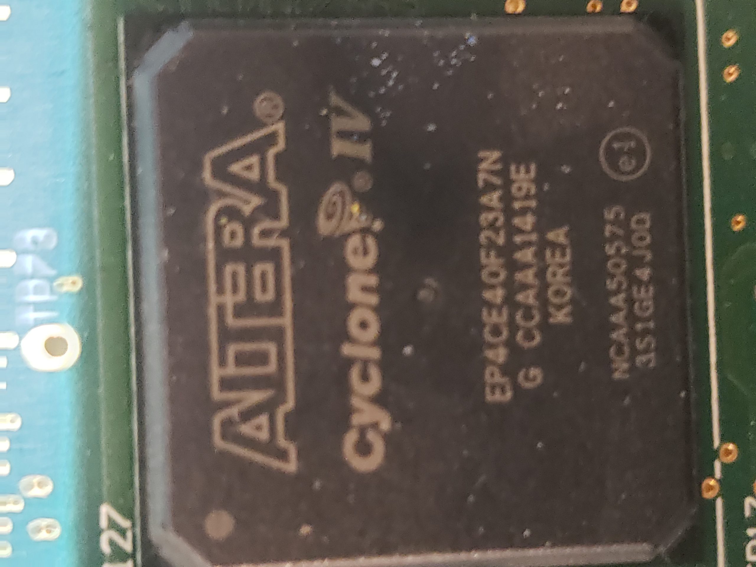
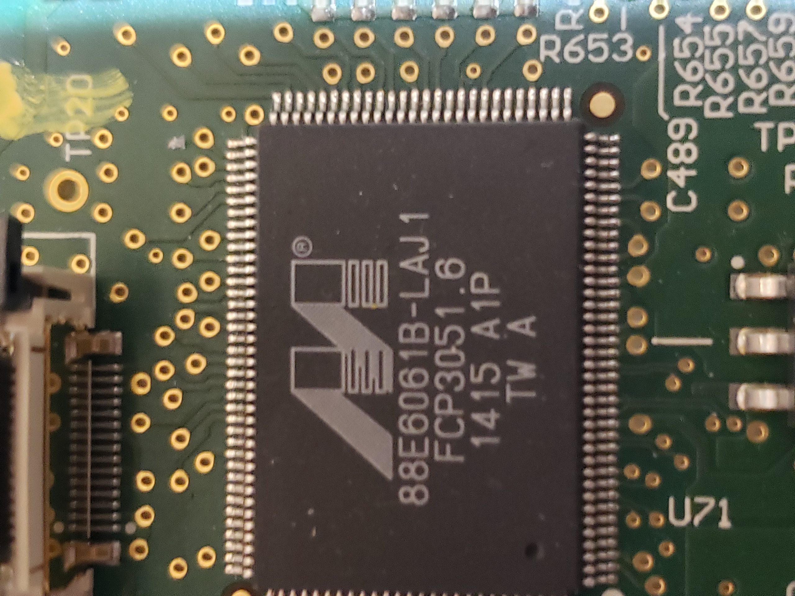
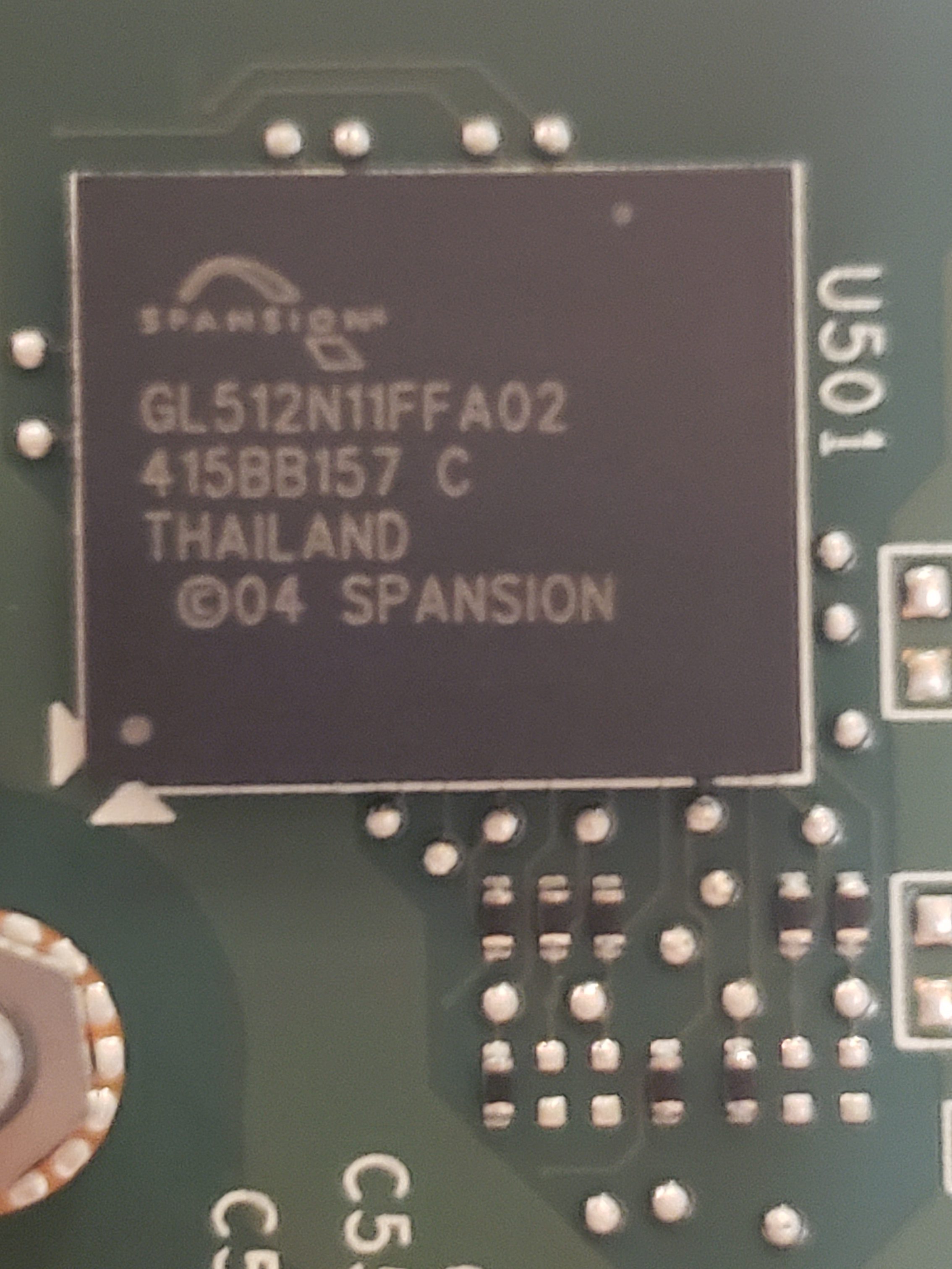
The infotainment process assembly is another “high value target” as this is the primary “brains” of the MCU. In addition to the NVIDIA processor, this board contains SDRAM, e-NAND Flash Drive*, a USB Hub, Ethernet controller, and an IC flash device. In additional to the components, on the board, there are a couple of unpopulated pads. Perhaps these pads are simply for optional components or perhaps they are for diagnostic purposes. More investigation is required to determine if they are of any value.

* – Due to how the Flash Drive has been utilized by Tesla, these devices are beginning to fail in older MCU 1 vehicles. When they fail, the MCU will operate erratically eventually resulting in the “black screen of death”. There is a recall and Tesla will replace these sub-assemblies with a newer/higher capacity flash memory. If you are skilled, you can repair this yourself. ☺

Main Board

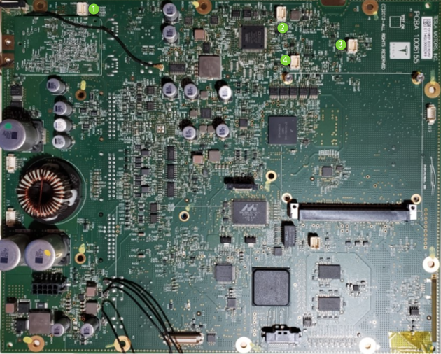
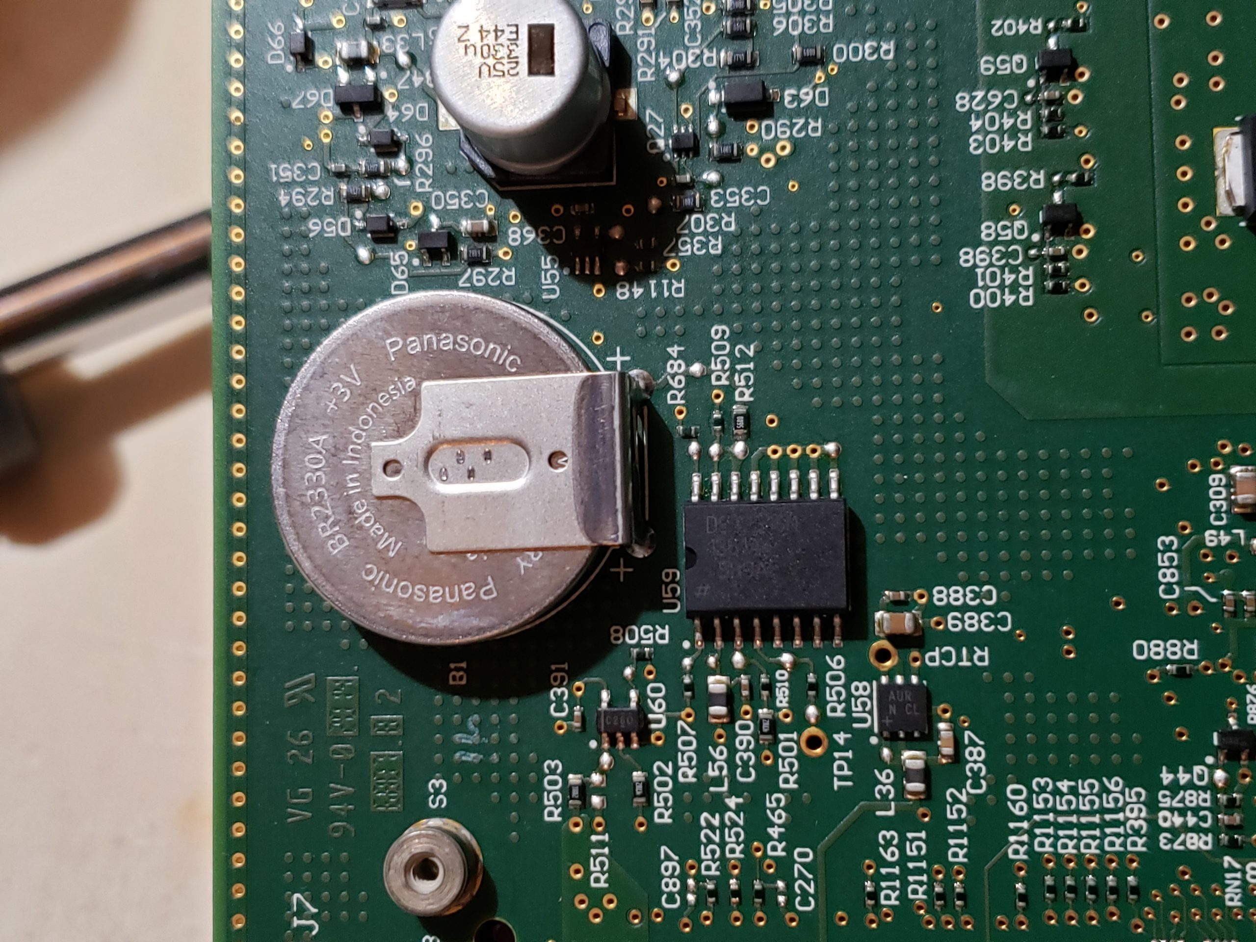
Given the size of the main board, it shouldn’t be surprising that there are many components of interest here. On this board, there are numerous communications chips: Switched gigabit Ethernet, multi-media serial links, CAN, and LIN. As I know the MCU plays “gatekeeper” for both Ethernet and CAN communications, reviewing these components for weaknesses will be a high priority.

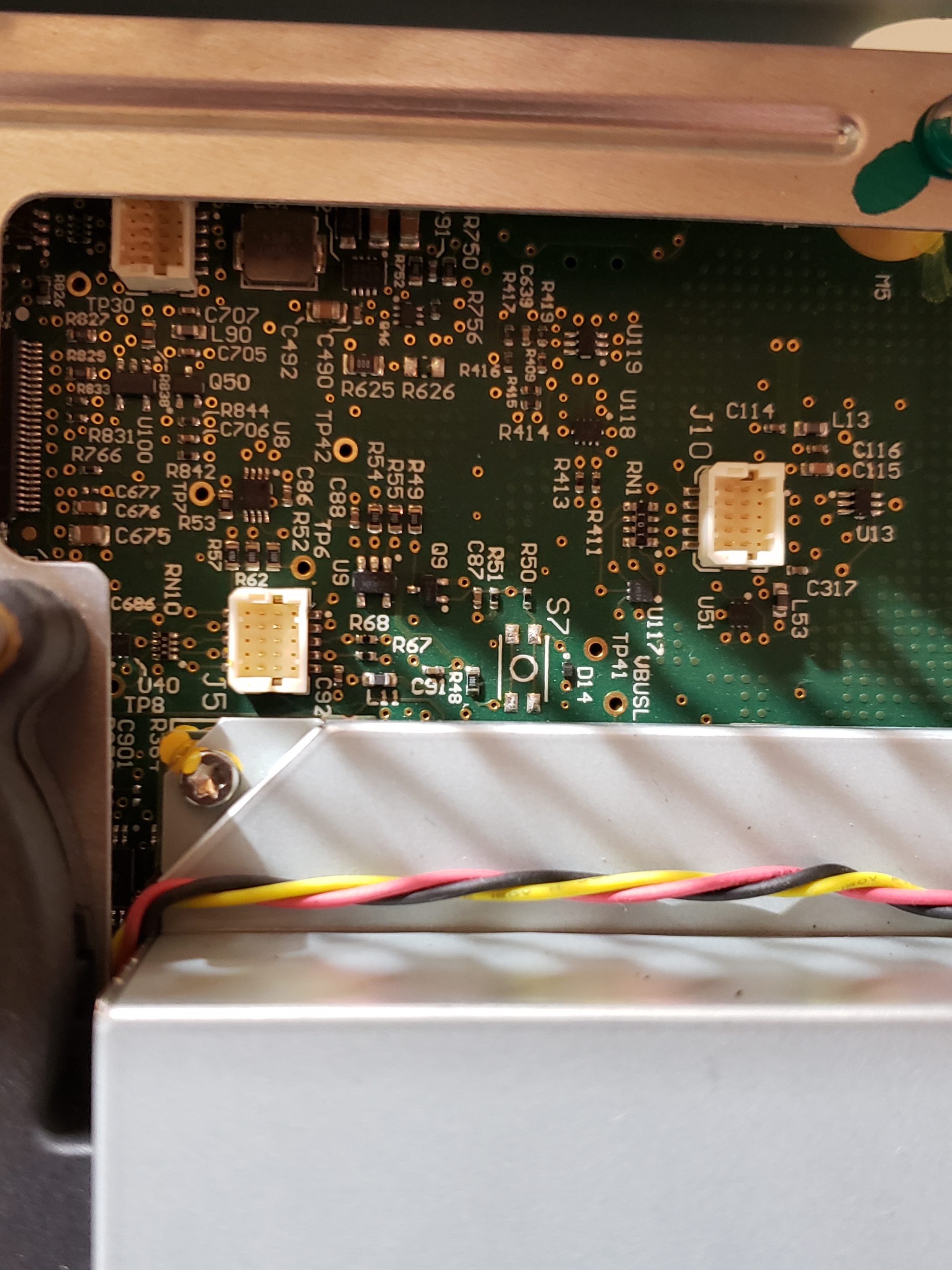
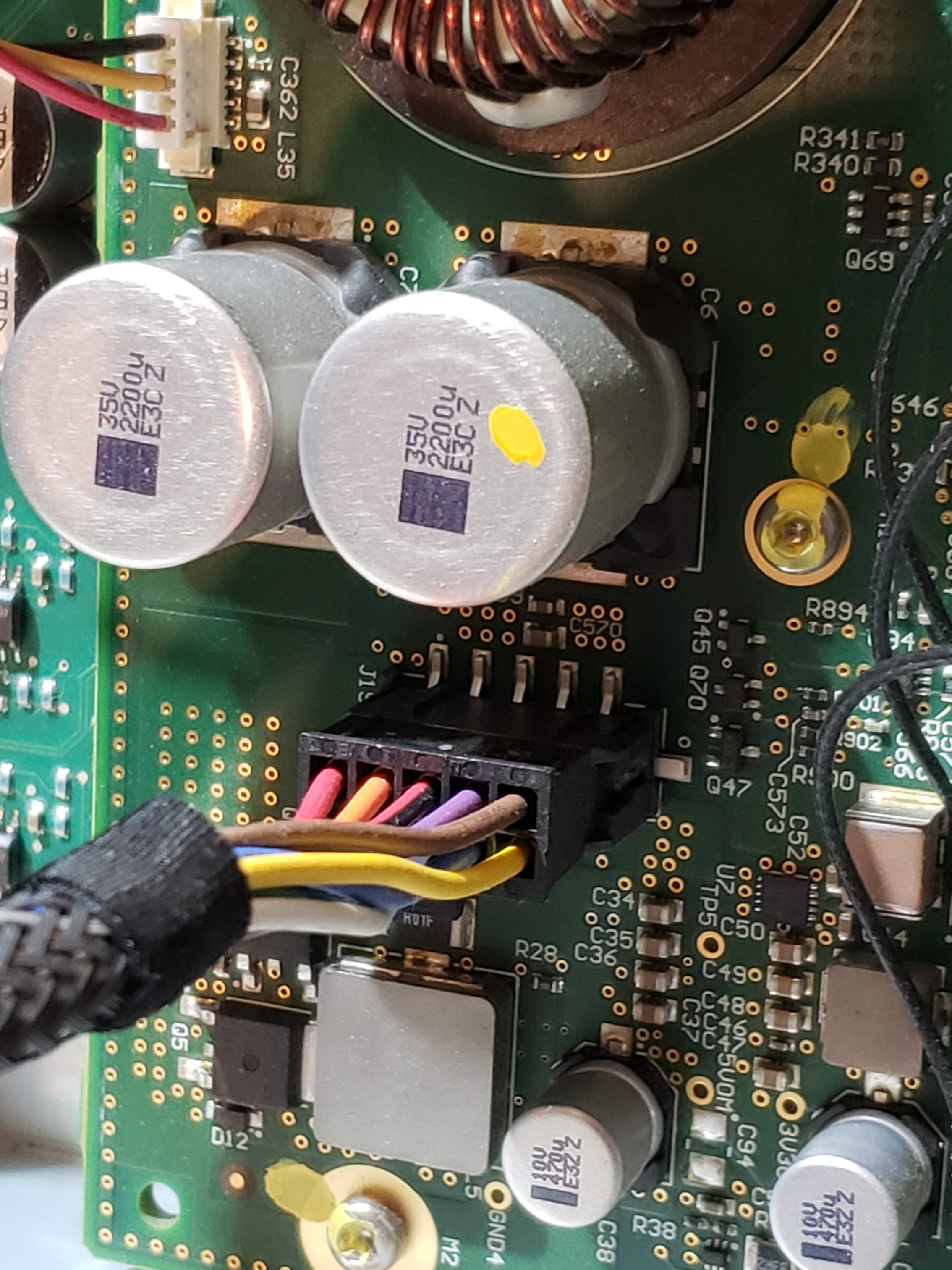
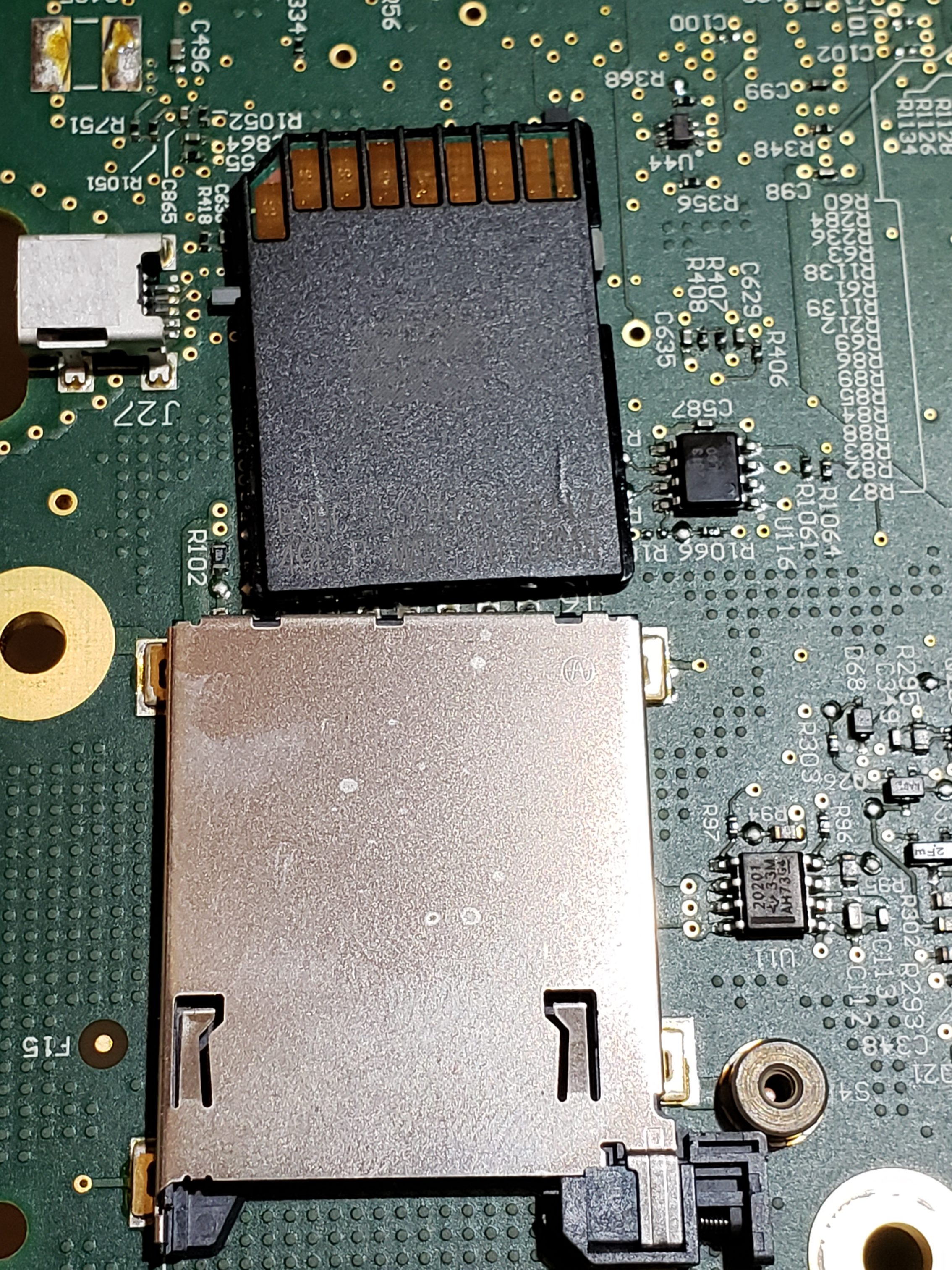
Aside from the communication ICs, this board also contains Micro SD & SD data cards, a hidden USB port, and multiple JTAG/TI diagnostic connectors. While I’m not going to “spill the beans” (yet) on the contents of the data cards, I will say there are both very useful for reverse engineering purposes. I will point out that NEITHER card is automotive/harsh environment grade. Because of this, they will fail much sooner due to the temperature extremes in a vehicle. If either of these cards fail, you are in for a very bad time!

C:\Users\317FX6~1\AppData\Local\Temp\SNAGHTMLa00f8bd0.PNG

“Ports of Interest”

As noted in the sections above, there are some connection points of interest. The following tables is a consolidated list for reference.

Next Post: Navigation Repair

In the next installment, we’ll dig into my Navigation Issue and how the information learned during this disassembly allowed me to ultimately resolve the issue.

Tesla Reverse Engineering: Creating a Bench Setup (MCU)

Overview

After growing up surrounded by cars, I’ve grown accustomed to doing my own maintenance and repairs where possible. When I transitioned to EVs a couple years back, I expected that some repairs may require more manufacturer involvement than I was accustomed to. Unfortunately, due to Tesla being DIY Repair unfriendly, the situation was worse than I expected.

Even more unfortunate, the local service center has struggled to provide consistent quality service trapping me in between a rock and hard place. One prime example was when my 2014 Model S’ navigation stopped functioning properly. After almost nine months of back and forth & no resolution from Tesla, I decided that this would be a good opportunity to dig into the computer system to see if I could resolve the issue myself.

As I didn’t want to tear my car apart (yet) and I prefer to be comfortable while experimenting, my first order of business was to setup a test bench in my “mad scientist lair”. Having this would allow me to analyze the hardware and the physical & software interactions between the various modules used in the vehicle.

While there are numerous modules in the vehicle, my primary point of interest is the Media Control Unit. (MCU). The MCU is the main unit in the Model S and is the obvious analysis point for my navigation issue. The goal of this post will be to simply get the MCU up and running on your bench. In later posts, we’ll dive into more thoroughly analyzing it and other modules.

Step 1 – Getting Parts

In order to run the MCU on your test bench, we’re going to need a few things:

  • An MCU! As it is unlikely you will have a spare laying around, acquiring this will be first on your shopping list. Acquiring directly from Tesla isn’t realistic, so you will be relegated to acquiring a used unit:
    • eBay – For the older MCU 1 units, you should be able to find a good number of them here
    • Car-Part.com – This site links you with salvage yards across the United States, Canada, and Mexico.
    • Facebook / Social Media sites – There are multiple “Salvage / Part” groups where individuals are selling parts.


Tesla Premium MCU 1 Part No

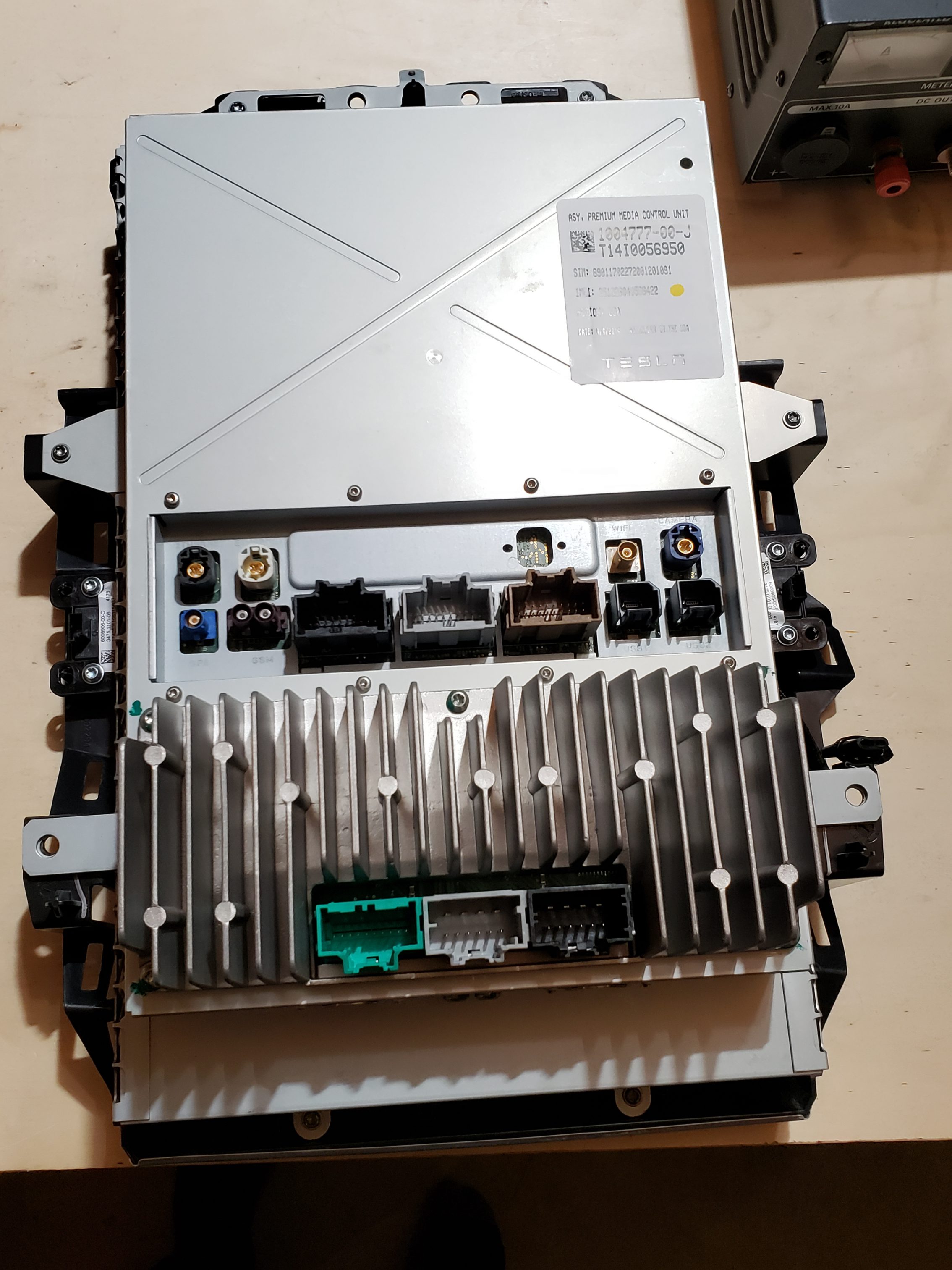
IMPORTANT: If at all possible, try to get the cabling/connects that plug into the back of the MCU. This will make life INFINITELY easier for you. At a minimum, you would want the connectors shown below for the “Premium” MCU 1 device:

Figure 2 – Minimum Required Connectors

  • Power – The MCU will require a steady 12V source that is capable of providing ~3 Amps.
  • Soldering Iron – While not absolutely necessary, having a good soldering station will allow for a cleaner setup. I use the Hakko 936 which is a reliable entry level choice.
  • Ethernet cable – A small Ethernet cable, that you won’t mind cutting up.
  • Speaker – A small automotive speaker for connecting to the MCU to enable audio playback. This isn’t absolutely necessary, but it is a nice to have.
  • Misc. Electronic Project cables / Jumper Cables – These will be used to create the Ethernet to Tesla MCU “Fakra” cable.

Step 2 – MCU Wiring

In order to get the MCU running on our bench, there are 3 three main items that we need to wire up:

  1. MCU Power & Ground : Required to provide power to the unit so that we can interact with it.
  2. MCU Speaker : Optionally recommended so that you can hear audio chimes and/or listen to music while you work. ☺
  3. Ethernet aka Fakra connection : Require so that we can startup the unit, access OS via telnet, or execute REST API commands.

MCU Power & Ground

Wiring up the MCU for power is actually very straight forward and only requires a few positive (12V) and negative connections spread across two of the connectors. The two connectors are located on the lower portion of the MCU and are commonly referred to as X425 (Black) and X426. (Grey)

NOTE: In order to keep your wiring to the Power Supply clean, I recommend using a distribution block for + and – connections.

Close-up of necessary MCU power wiring connections.

MCU Speaker

While you can wire up as many speakers as you would like, we only need the center speaker so that we can hear alert tones, etc. This speaker is also located on the X425 (Black) connector.

The easiest way to connect the speaker to these cables is to simply strip off the ends and use alligator clips:

Ethernet aka Fakra HSD connection

While the Tesla MCU utilizes Ethernet for certain actions, it does not provide you a convenient RJ45 port. The Ethernet connections utilize a “Fakra HSD” connector.

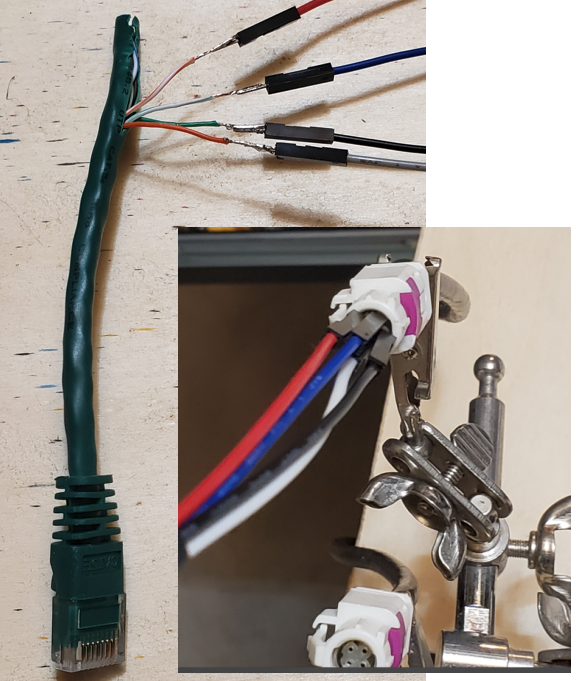
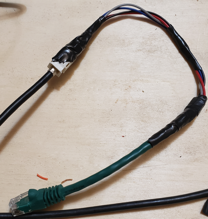
While you can buy these cables pre-made for ~$50, you can make one relatively easily once you know how to map out the HSD pins to the Ethernet cable wire.

The HSD cable consists of 4 pins consisting of two diagonal wire pairs where D+ / D- & Vcc / GND are pairs.

While a standard Ethernet cable consists of 8 wires / 4 twisted pairs, only 2 pairs are typically needed and these two pairs will be matched up to the HSD pinout as follows:

If making your own cable, the jumper wires I recommended at the start of this blog fit perfectly into the Fakra connector. I simply soldered one end to the Ethernet cable, inserted the other into the Fakra connector, and then taped it to ensure it doesn’t come loose.

C:\Users\317FX6~1\AppData\Local\Temp\SNAGHTML20204360.PNG

Step 3 – MCU Startup

Once you have completed all of the wiring in the previous step, you are ready to start the MCU! Next, perform the following actions:

  1. Ensure that you have connected your positive and negative wires to your power supply and that the power supply is set to a 12V output voltage.
  2. Ensure that your speaker is connected.
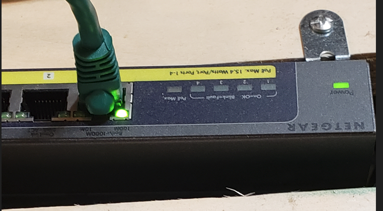
  3. IMPORTANT: Plug the Fakra/Ethernet cable into the back of the MCU and into either a network device (Hub/Switch) or to a laptop. Even if the MCU has power, it may not fully start unless it sees network traffic. [There are other ways to force it to start, but this is the easiest]

  4. Turn on your power supply – You will notice that at first, it is drawing a relatively low amount of amps, but once it fully starts, you will see the draw increase.
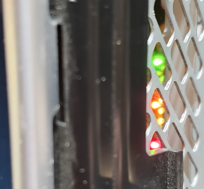
  5. Verify that MCU has power – If you look at the right side of the unit, you should see multiple LED status lights. Initially some will be Yellow/Red. Some will turn green as unit boots, etc.
  6. Wait…. Wait…. Wait… It should take ~20 – 30 seconds to full boot up. If you have the speaker connected, you SHOULD hear a series of chimes around the same time the Tesla ‘T’ appears.
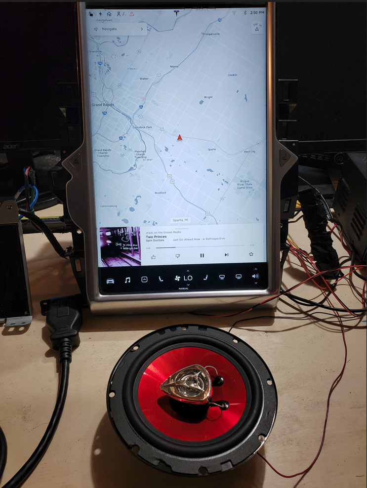
  7. Wait… Wait… Wait some more and then you should finally see the MCU come to life
    Congrats! You now have a functional MCU on your test bench!

EPM Automate – State Management “Public Safety Announcement”

Overview

EPM Automate is an Oracle provided command line interface which is used for interfacing with Oracle Cloud EPM applications. These applications expose REST API endpoints for consumption to accomplish a wide variety of activities. (data loading, user management, maintenance, rules execution, etc., etc., etc.) The EPM Automate utility allows users to consume the REST API endpoints without having to write writing code. This is useful for application administrators and power users who wish to perform certain activities without having to navigate the applications graphical user interface. The utility can also be utilized by automation processes to reduce technical debt/maintenance overhead since it abstracts the API details.

Using EPM Automate is relatively simple as you just download/install the utility, on a Windows or Linux system, and issues commands via the command line. Commands are issued one after another in the necessary sequence to perform a particular task. In the example below, I am connecting to an EPM Cloud application, requesting the value of a substitution variable, and then logging out of the application.

After logging into the application, you can run as many individual commands as you would like and you can leave you ‘session’ open for some time w/o having to provide authenticate again. Even though the underlying API calls are executed separately, and you are not providing credentials for each command issue, the EPM Automate utility is maintaining state behind the scenes.

While this approach is convenient for the user, it is important to understand how this is being accomplished as misuse can result in potentially serious issues! The purpose of this post is to educate you on how EPM Automate State Management behaves and how to avoid any serious issues based on its design. Additionally, I’ll provide some future update thoughts which could address the concern raised here.

State Management

State Management is accomplished through a text file called .prefs. This file contains all of the relevant information that EPM Automate requires to communicate & authenticate with the REST API. The file is created after you successfully execute a ‘login’ command in EPM Automate.

In the early releases of the utility, Oracle stated that you should not run more than one instance of this utility at the same time. While they didn’t elaborate as to why, the issue revolved around the .prefs file. While they have made updates to the application to help address the issue, there are still some gaps which could lead to undesirable consequences.

The (mostly resolved) Issue

The issue with the .prefs file occurs when you have more than one instance of EPM Automate concurrently in use on the same machine. Originally, the .prefs file was placed in a fixed folder meaning that all instances would be reading/writing the same file and the last successful login attempt by any user on the machine would overwrite the others! If those sessions were working against the same application, not a big deal; however, if the sessions were interacting with different applications, this would be bad. The best movie analogy would be Ghostbusters’ “DON’T CROSS THE STREAMS!”

Since the original version of EPM Automate, they have adjusted this logic to allow for concurrent execution by different users. To accomplish this, the .prefs file is moved under a hidden subfolder which reflects the logged on user’s information.

By keying off of the username, this ensures that separate users will not have a collision and can operate safely.

But what happens if the same user wants to be super-efficient and do work on two different Cloud EPM applications concurrently? (it will depend, based on how careful you are!)

Crossing the Streams, for Science!

To demonstrate what could happen, we will open two separate Command Windows and just jump right into issue EPM Automate commands.

Before issuing EPM Automate commands, I’ve added a global substitution variable “ServiceInstanceName” which will hold the service instance name to two FCCS applications.

After creating the substitution variables, we will connect to one application at a time and query the substitution variable to see what we get

Next, let’s do the same thing for the second server:

Now, let’s go back to the first window and query the variable again.

As you can see above, running two concurrent processes as the same user can lead to some undesirable results. While my example is simply reading a variable, imagine what would happen if you logged into a second application and triggered a wipe/reset of the 1st? Oops!

Easy Workaround

Fortunately, there is an easy workaround. Before starting your EPM Automate sessions, ensure that you are working from different folders and all will be fine since the .prefs files will be created in different locations.

Future Update Thoughts

To fully prevent this issue from impacting interactive users, EPM Automate could append the Process ID (PID) to the folder name which houses the .prefs file. This would ensure that each & every command window has a distinct folder/file.

While this would be a quick/easy fix for interactive users, this would create a potential headache for anyone who is using EPM Automate in a non-interactive manner if EPM Automate commands are being issued in separate sessions. (e.g., AutoSys, Control-M, etc.). To address this, Oracle cloud add an optional command line parameter (“prefsfile”) to allow for explicitly setting the location of the .prefs file.

Retro Computer (Compaq SLT/286) “Steak Knife” Repair

Overview

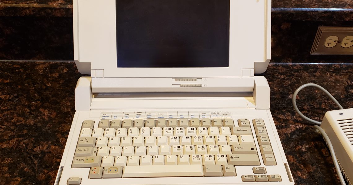
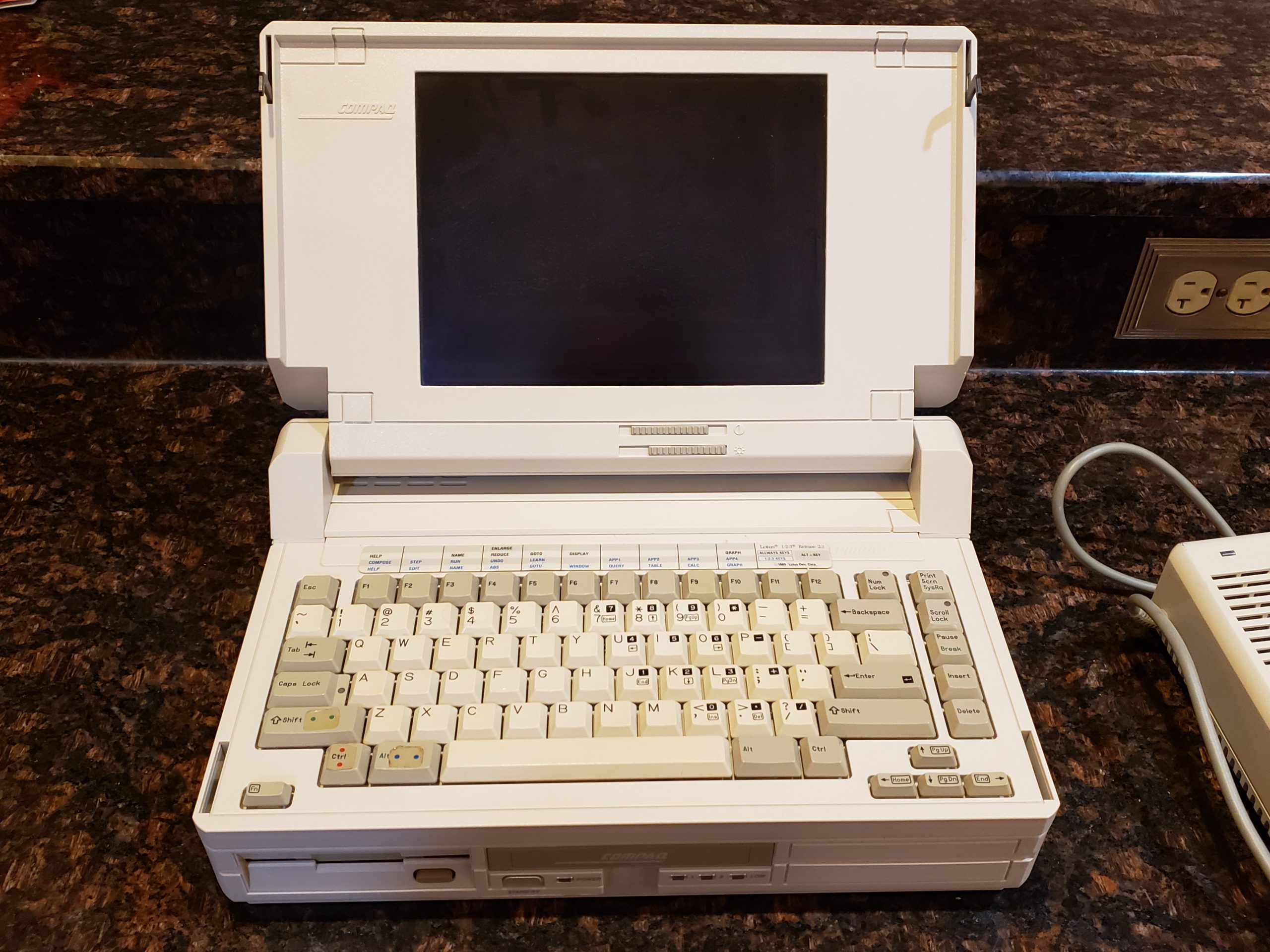
Recently, I ran across someone looking to sell an “ancient” laptop that had been long forgotten in their closet for ~30 years. The laptop in question is a Compaq SLT/286. As I’m a sucker for very clean old tech, this was right up my alley! Since it was a Compaq machine, I was especially interested as I have a few of their previous ‘portable’ machines as well.

When I inquired about the machine, the owner state that it turns on perfectly fine; however, they were not able to do much else since it doesn’t ‘boot up’. The person stated that it was a work machine that was upgraded and prompt left, in its original bag, in their closet and was only recently discovered.

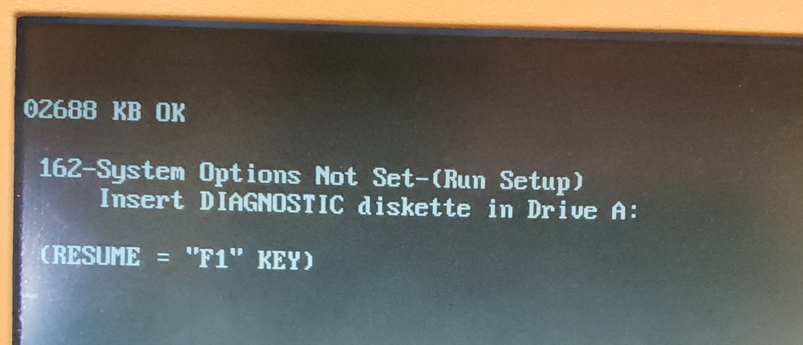
When I plugged in the machine, it did start up immediately; however, I was presented with a very familiar error message:

Issue

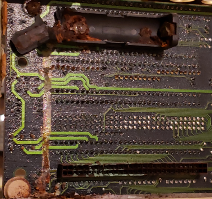
This error message is a clear indicator that the machine had “forgotten” certain configuration settings. In older computers, these Basic Input / Output Services (BIOS) settings are stored in a Complementary Metal-Oxide-Semiconductor. (aka CMOS) The CMOS requires a small amount of power to retain its memory. The earliest PCs typically had a small battery attached to the motherboard which would provide this power. Unfortunately, batteries do not last forever and will fail. In a best case scenario, the battery simply fails to produce enough power while in worst case scenarios, the battery loses integrity and acid can damage the motherboard.

Worst Case Example: Compaq Portable II w/ catastrophically failed battery

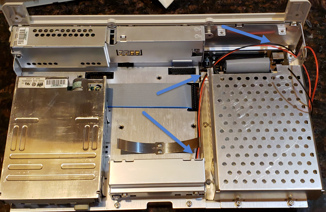
Fortunately, this Compaq model did not use a battery that could fail in such a manner and the motherboard was clean as a whistle. (see all the disassembly pics at the end to see just how clean this machine is!)

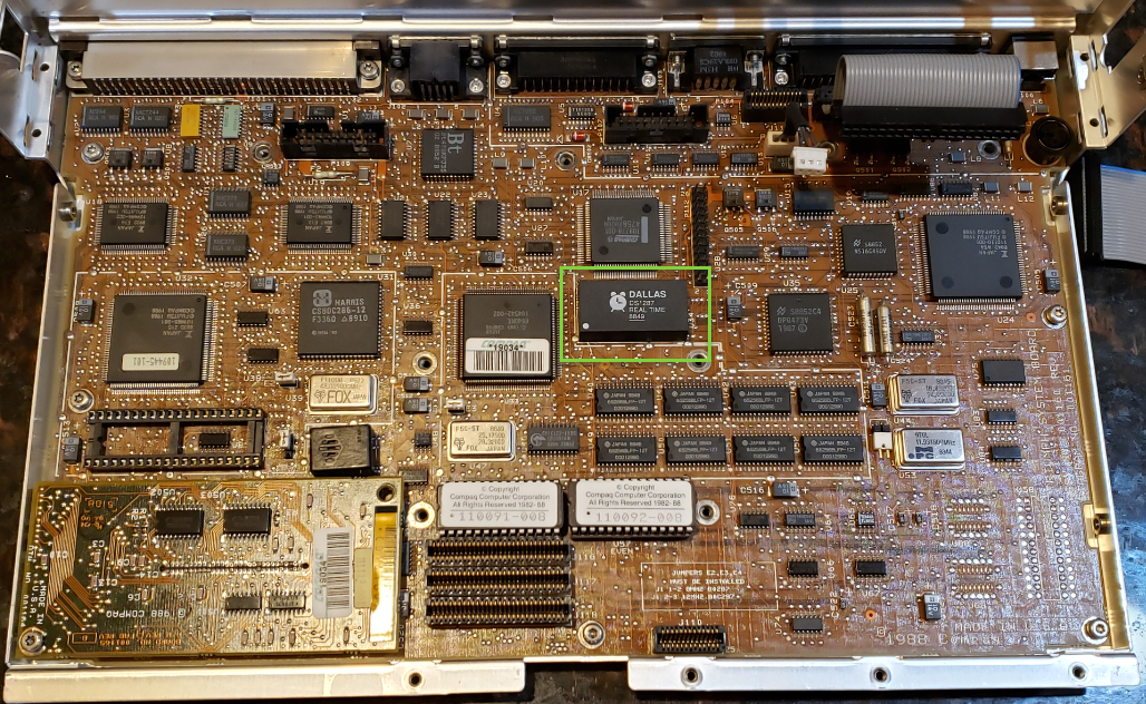
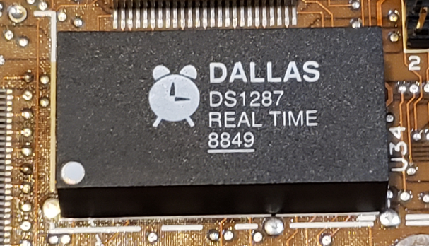
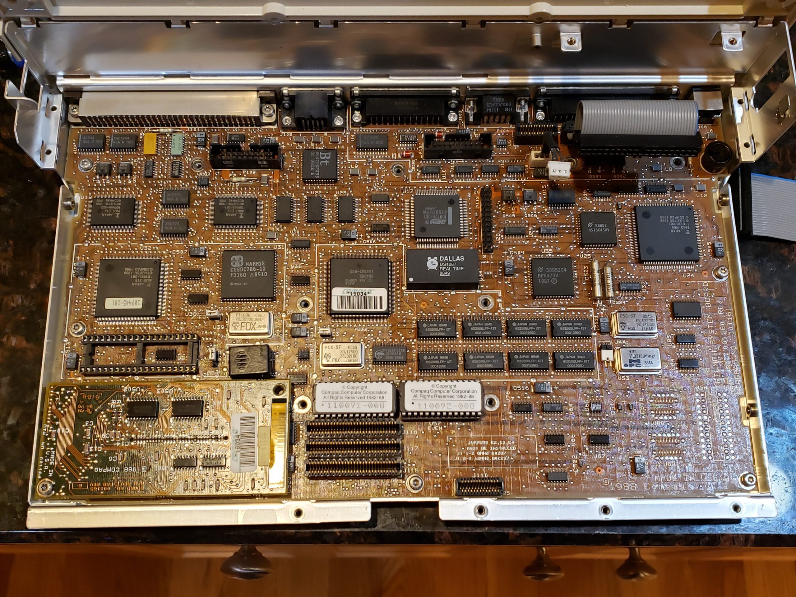
A quick scan of the motherboard also reveals that there isn’t a battery per se. For this computer, Compaq chose to use a Dallas Real Time Chip (RTC) module which stores the relevant information. This device, which is still used to this day in certain applications, performs multiple activities: “nonvolatile” RAM memory, supports certain Read Only Memory (ROM) operations, and Real-Time Clock (RTC) operations. The one “gotcha” to this device is that the RAM is non-volatile only because there is a battery hidden inside the module which provides power to the device. Once this internal battery is depleted, it is no longer a nonvolatile RAM device.

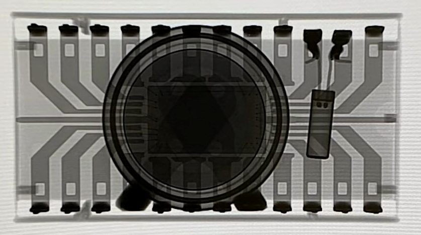
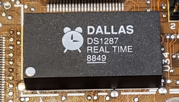
The image on the left is the module found on this Compaq’s motherboard. The ‘8849’ is the build date for the module which corresponds to the 49th week of 1988! The image on the right is an X-Ray of this type of module. The power source is the circular item near the middle of the module. (X-Ray image courtesy of https://ardent-tool.com/)

CMOS Repair

In order to get this PC up and running, we will need to address this failed module. There are a few options:

  • Replace the Dallas RTC module with a newer one
  • Carefully modify the existing Dallas module to power it from an external source

As with any repair, there are always trade-offs to consider. In this scenario, I chose to supply external power to the existing module for the following reasons:

  • The existing module is directly soldered to the motherboard. This would require me to desolder the existing module and then solder a new one to the board. While this is not overly difficult, it requires a bit more effort and care than the other option. (If Compaq had placed the module in a socket, I would have opted to replace the module)
  • Many suppliers of compatible Dallas RTC modules are selling “New Old Stock” (NOS) components. Because of this, the batteries may only last for a few years before requiring replacement again.
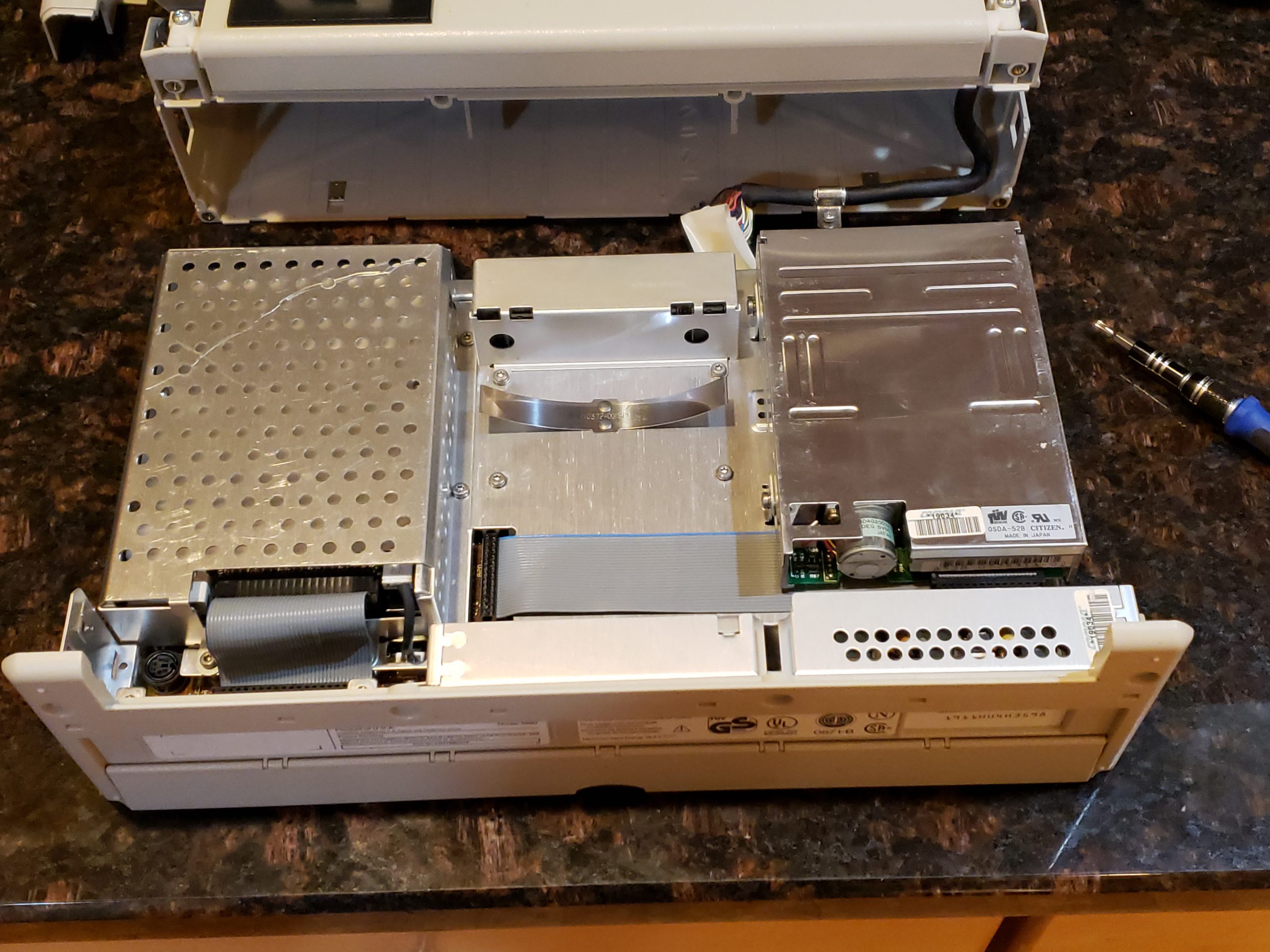
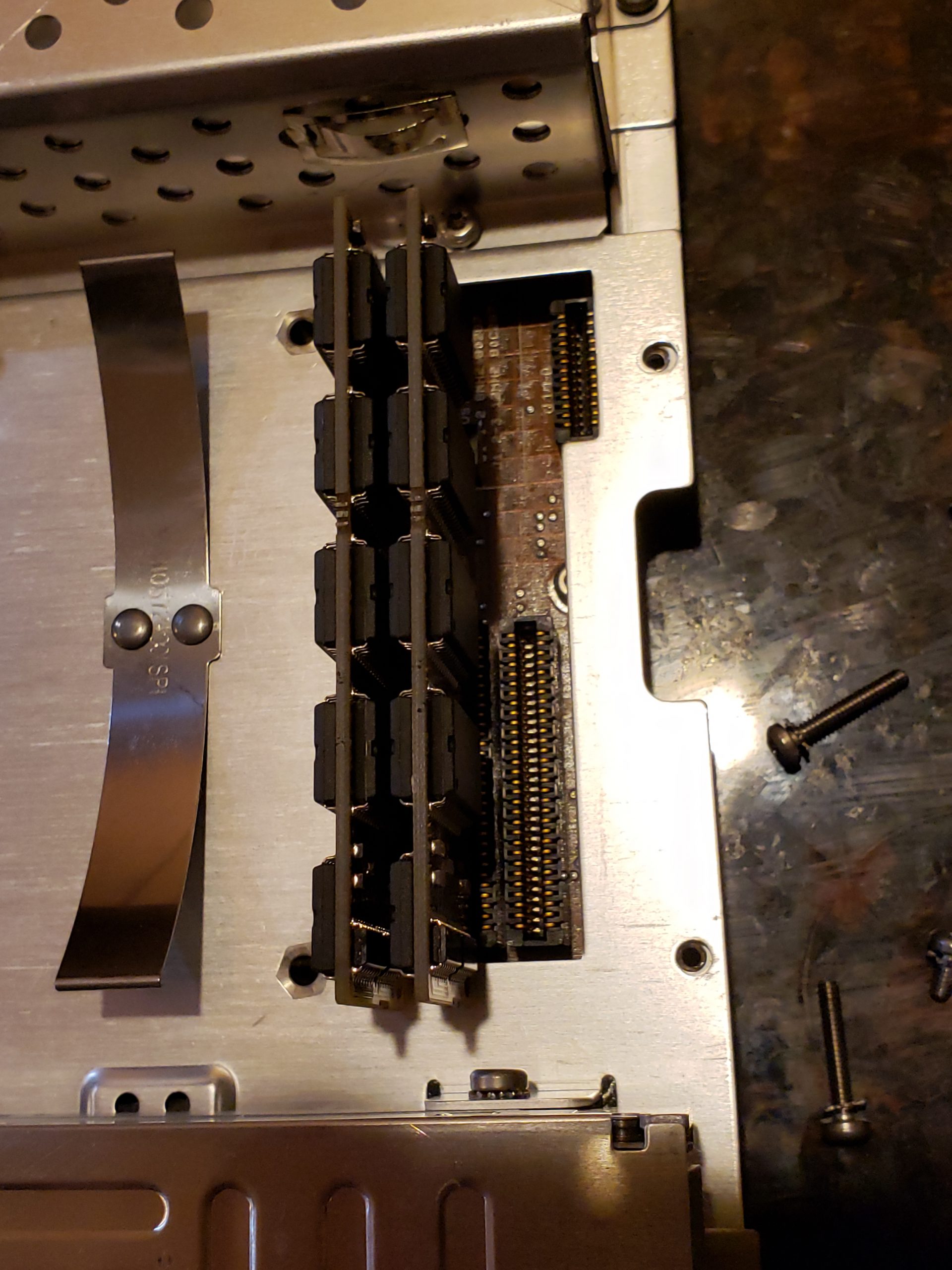
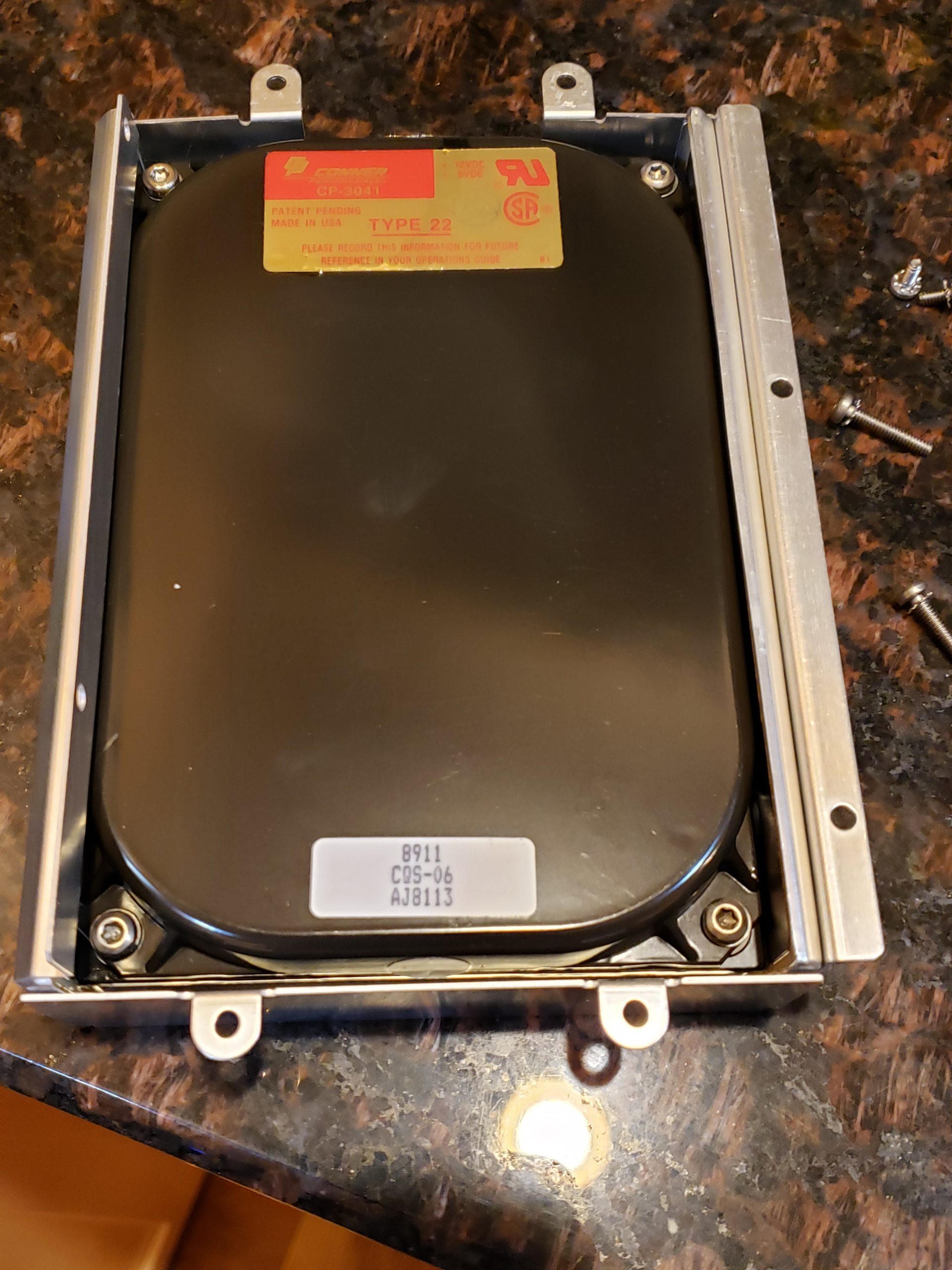
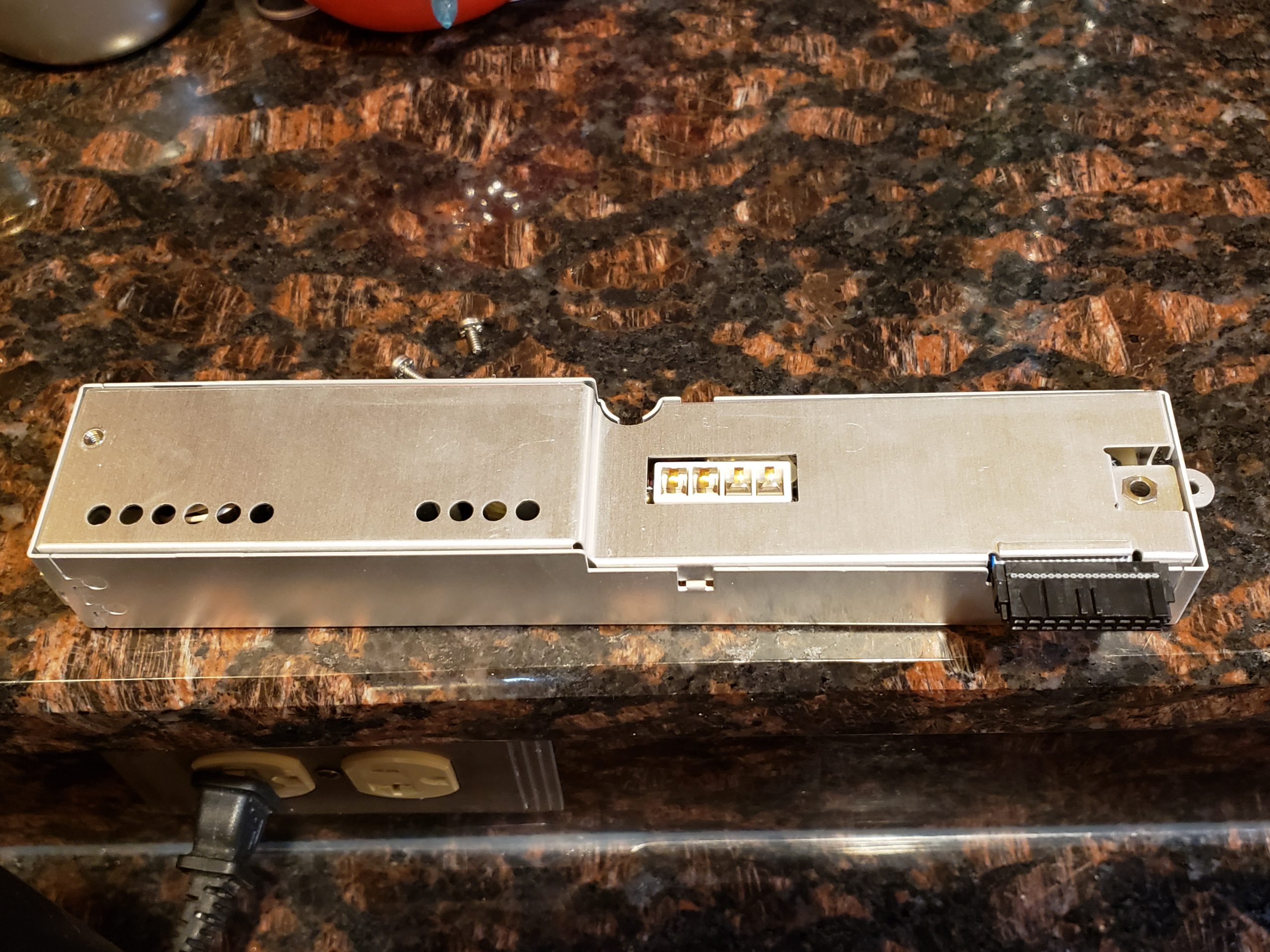
  • Accessing the module requires a complete disassembly of the unit. (disassembly pictures are in a later section)
    • If I’m going to have to replace a battery again, I’m strongly prefer to *NOT* have to disassemble the unit
    • NOTE: As you’ll see later, my repair allows for a 60 second battery replacement and requires no tools.
  • This approach is relatively low risk. If I make a mistake accessing the internal battery, I can always resort to replacing the module. If someone else acquires this machine and would rather replace the module, they can still do this.

The following steps were performed to implement the external battery solution:

  1. Carefully remove the top layers of the Dallas module’s epoxy to expose the battery
  2. Disconnect the battery from the module pins
  3. Solder new leads to the power pins
  4. Route wires to a convenient location
  5. Solder coin battery holder to other end of leads, add battery, and verify power

Module Modification

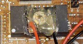
If you’ve read this far, you are probably wondering: “Why did Charles mention he used a steak knife to effect this repair”? If so, you don’t have to look any further! To cut into the module, I choose to use a nice and sharp steak knife! While a Dremel would have been more surgical, it was in the garage and I didn’t feel like trekking into the cold to fetch it. As the epoxy/resin material is relatively soft, I had no trouble using a knife to accomplish this task. Once the battery was exposed, a small wire cutter was used to disconnect the existing battery. Next I prepped some wires, soldered them to the appropriate pin outs, and sealed it with my glue gun. (Yes, I could definitely have made this cleaned, but I wanted to make sure it was working first…)

Wire Routing & External Battery

I gave myself plenty of extra wire so that I could route it to a spot where it wouldn’t impact the operation of the laptop *and* it could be easily accessible.

(Look how clean this unit is! Amazing)

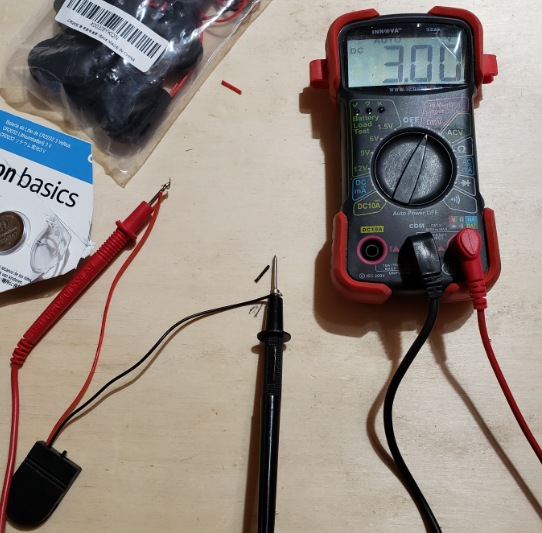
I then put together the coin battery holder and verified that I was getting proper voltage.

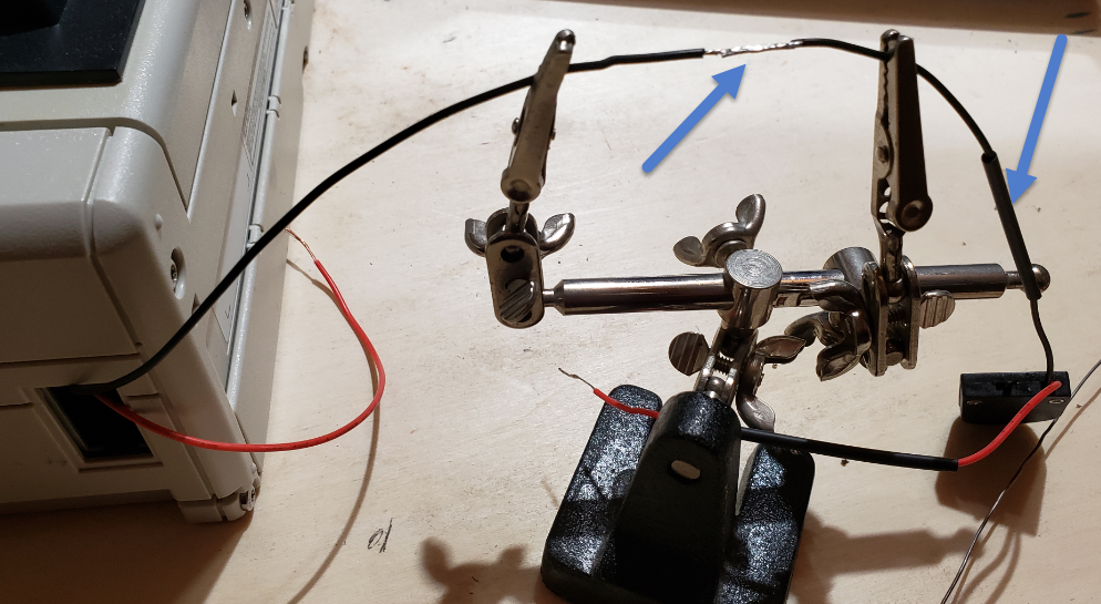
Next, I soldered the coin battery holder to the module wires. (Always use heatshrink!)

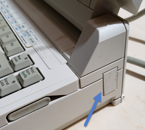
Finally, I wrapped the holder in electrical tape and tucked this into the access port on the side of the laptop. This convenient location will allow a battery swap in seconds without the need for any tools. If I add the optional model, I will need to relocate this; however, it is a perfect location for now.

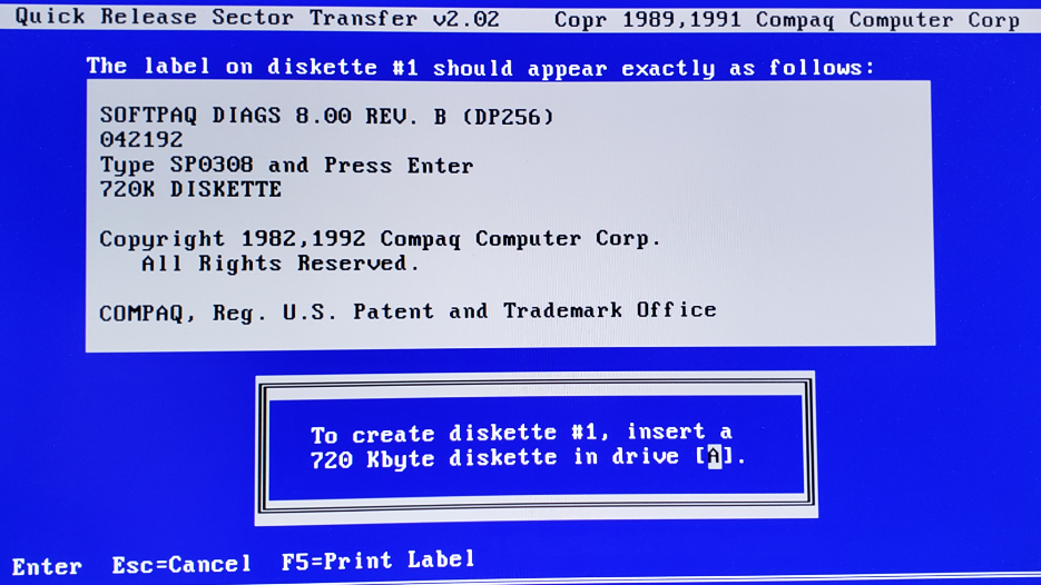
With the machine physically repaired, the only thing left to do is create the Compaq Diagnostic Disk and reconfigure the device.

Software Reconfiguration

After scouring the internet, I was able to locate the appropriate software and used it in yet another retro machine to create the necessary software:

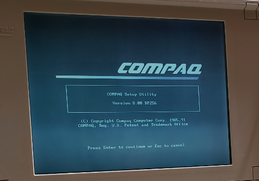
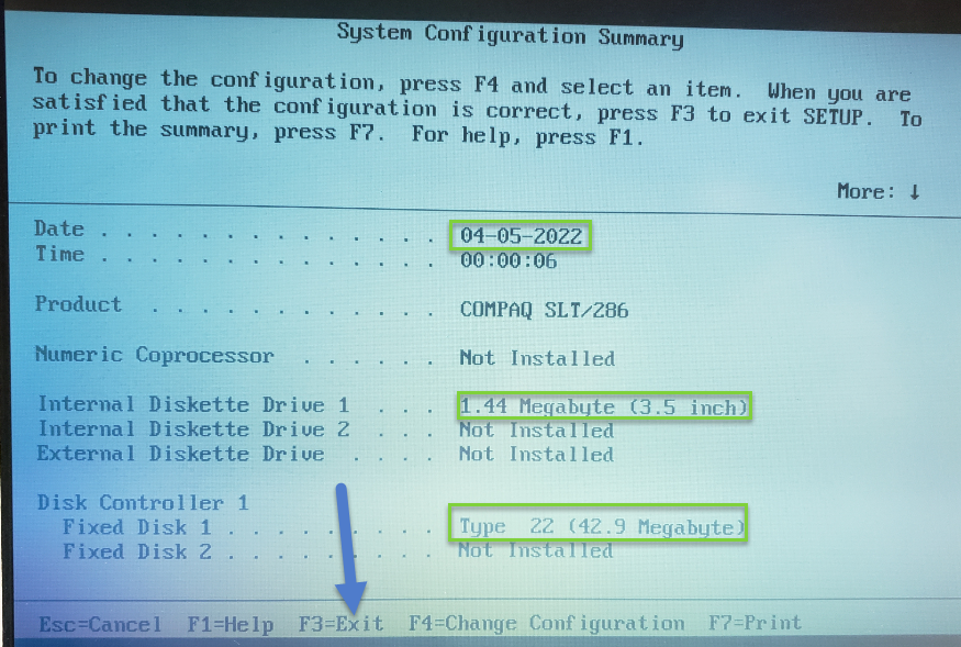
I insert this newly created disk into the Compaq, turned it on, and the configuration utility started. The utility seemingly auto-detected everything auto-magically.

After saving the configuration, the machine started up w/o any error messages!

It Lives!

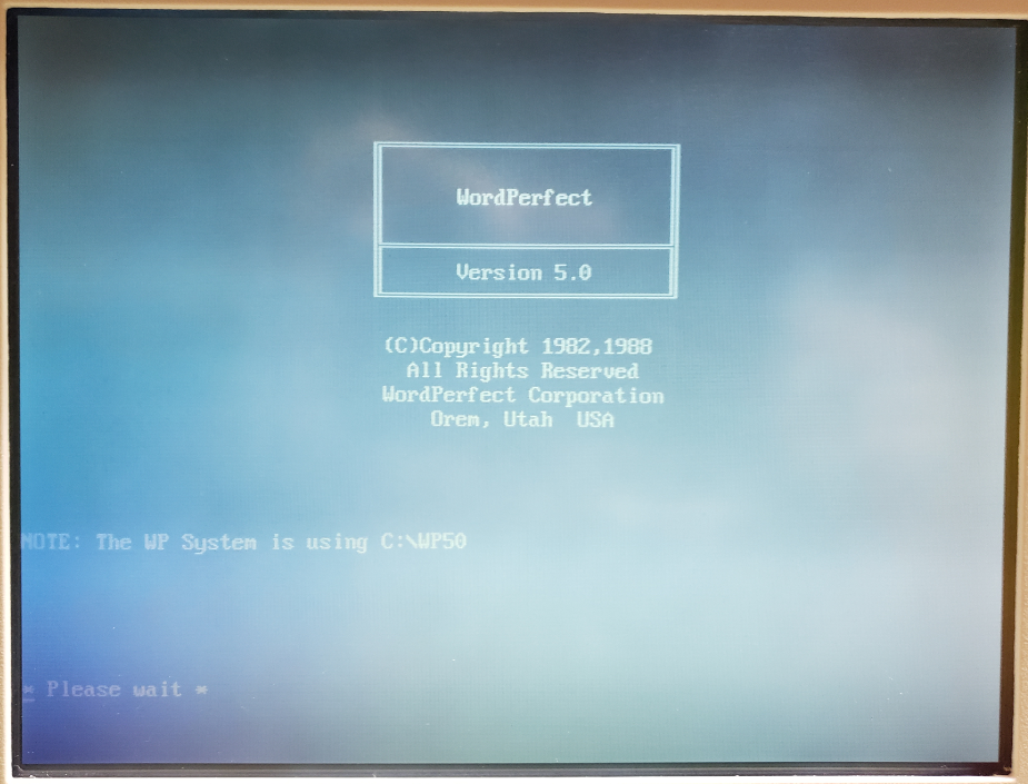
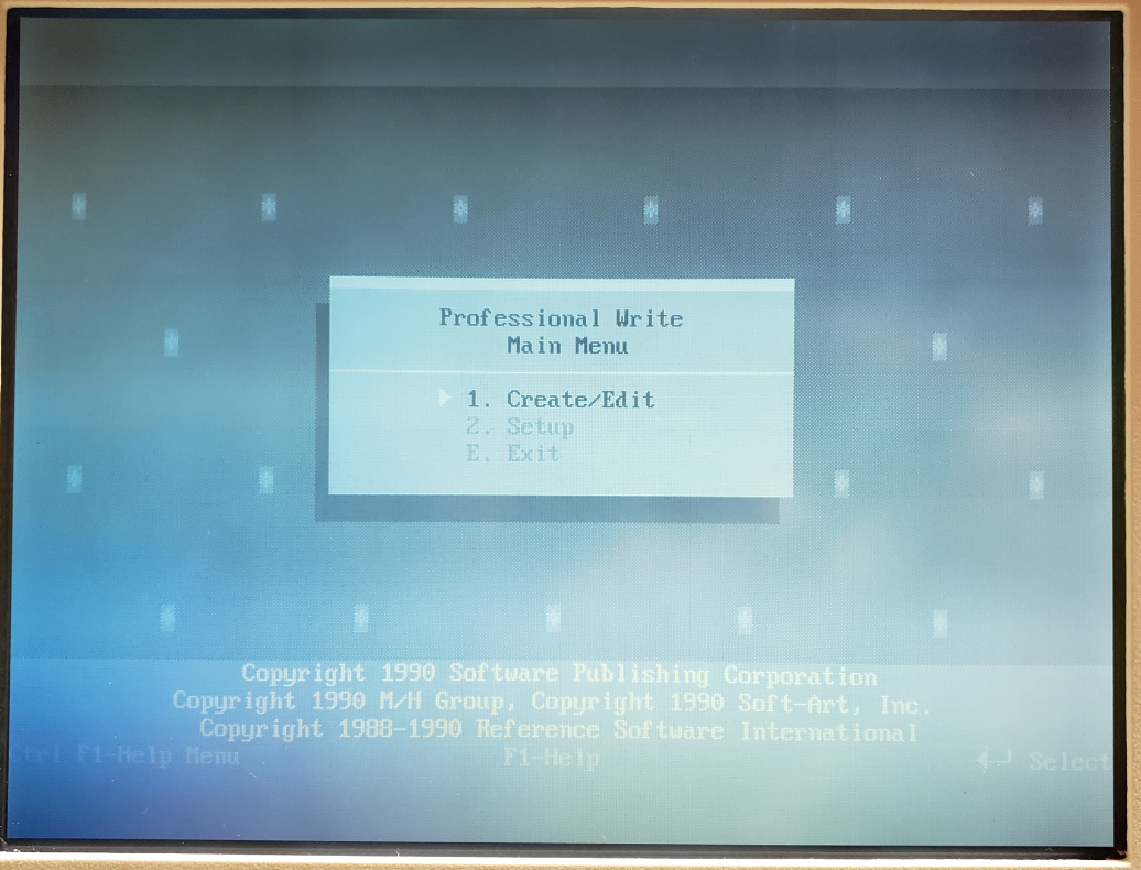
After exiting the configuration utility, the computer sprang to life and I was greeted with a DOS prompt. Looking around on this machine, I found some pretty standard late 1980’s business programs. Quite a trip down memory lane.

1-2-3

WordPerfect

PFS Write

Bonus Pics

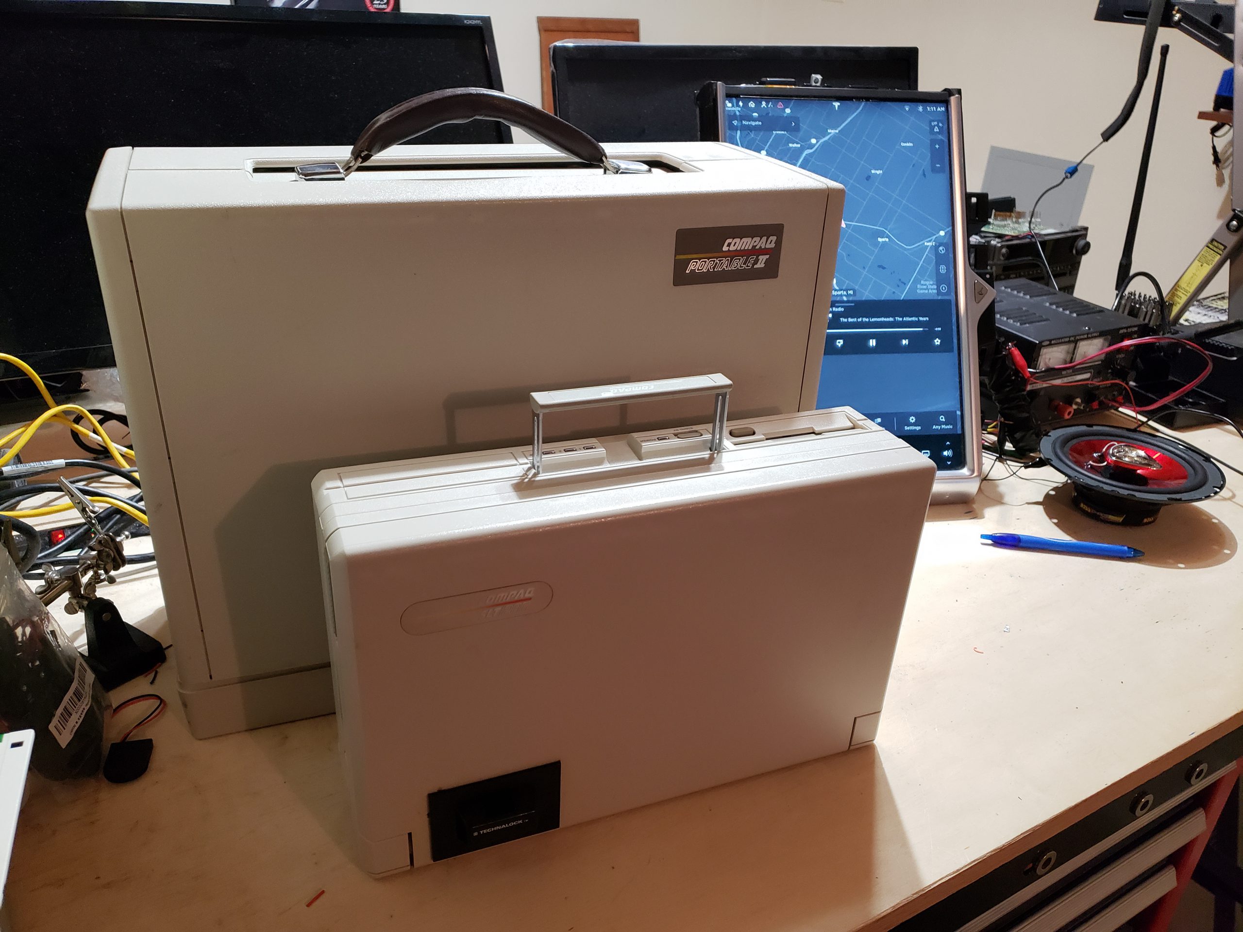
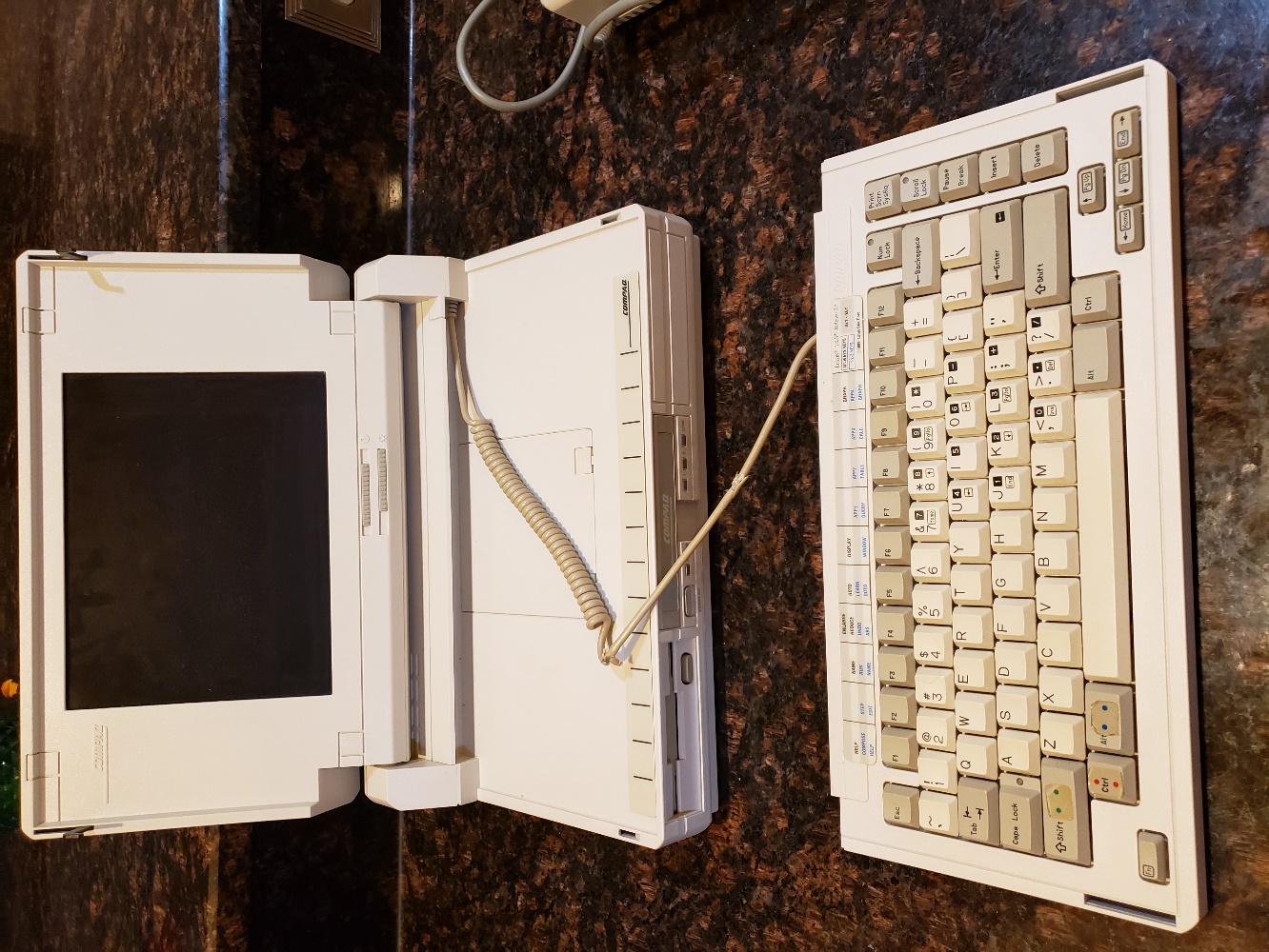
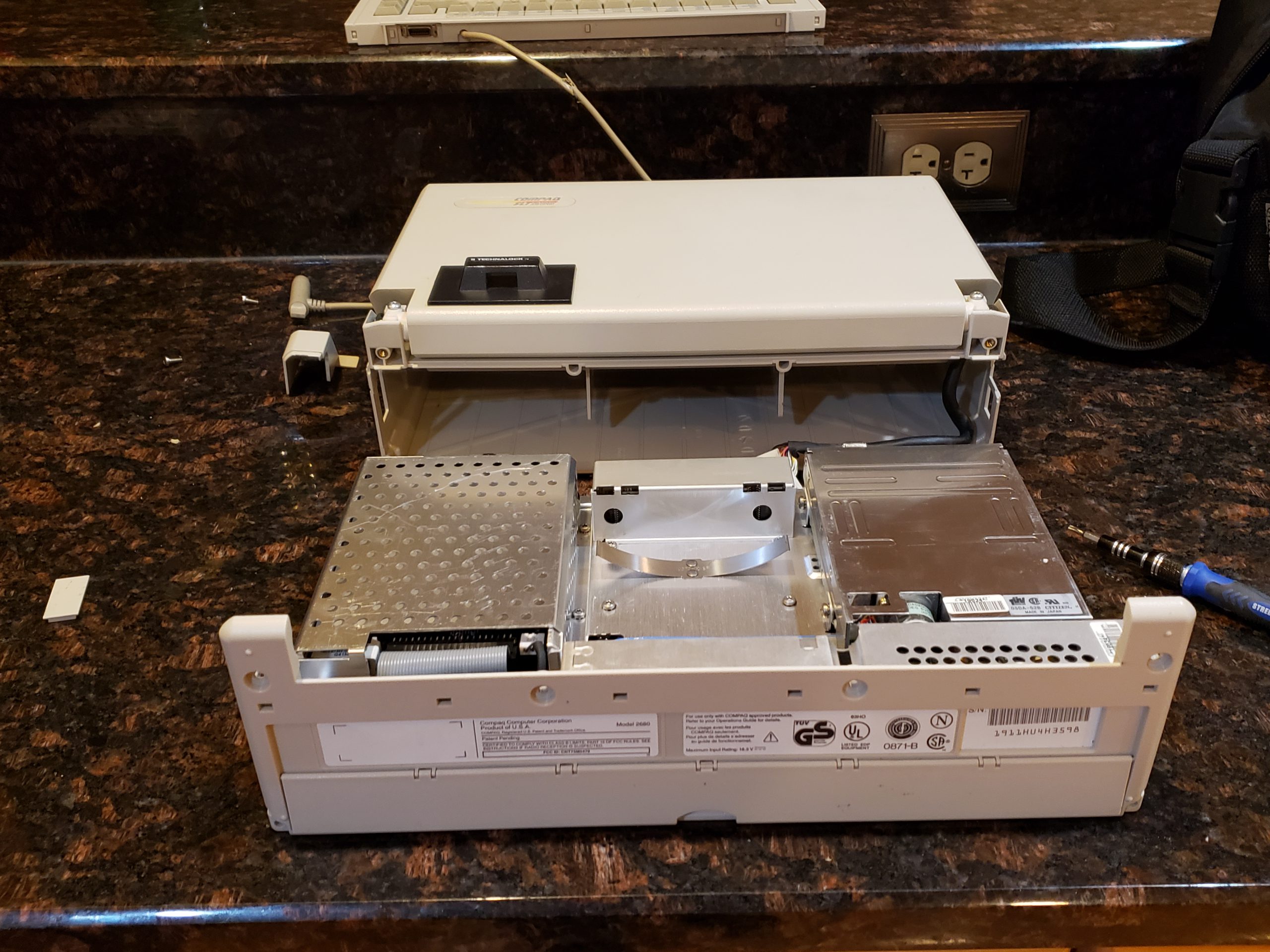
Below are disassembly and other pictures that didn’t make the cut up above. Take a look at how clean this machine is. Amazing for the age. Also, if you made it this far, there is a hint for my next post. Something else running on that workbench is a bit out of place….. If you recognize it, feel free to point it out and take a guess what we’ll be doing with it!

Compaq Portable Family

The largest machine is only a couple years old. Amazing at how much they shrunk down the electronics! Another post is going to dig into that machine and you will be able to see the difference!

Disassembly


Natural Language Processing (NLP) Overview Sentiment Analysis Demo – Twitter / Stock

[NOTE – This post covers NLP & Sentiment Analysis at a very high level and is not intended to be an ‘all-inclusive’ deep dive in the subject. There are many nuances and details that will not be discussed in this post. Subsequent posts will dive into additional details]

NLP Overview

While modern computers can easily outperform humans in many areas, natural language processing is one area which still poses significant challenges to even the most advanced computer systems. For instance, while people are able to read Twitter posts about a given company to infer a general sentiment about the company’s performance, this type of interpretation is challenging to computers for a multitude of reasons:

  • Lexical Ambiguity – A word may have more than one meaning
    • I went to the bank to get a loan / I went to the bank of the river to go fishing
  • Part of Speech (POS) Ambiguity – The same word can be used as a very / noun / adjective / etc. / in different sentences
    • I received a small loan (noun) from the bank / Please could you loan (verb) me some money
  • Syntactic ambiguity – A sentence / word sequence which could be interpreted differently.
    • The company said on Tuesday it would issue its financial report
      • Is the company issuing the report on Tuesday or did they talk about the report on Tuesday?
  • Anaphora resolution – Confusion about how to resolve references to items in a sentence (e.g. pronoun resolution)
    • Bob asked Tom to buy lunch for himself
      • Does “himself” refer to Bob or Tom?
  • Presupposition – Sentence which can be used to infer prior state information not explicitly disclosed
    • Charles’ Tesla lowers his carbon footprint while driving
      • Implies Charles used to drive internal combustion vehicles

For reasons, such as those shown above, NLP can typically be automated quite well at a “shallow” level but typically needs manual assistance for “deep” understanding. More specifically automation of Part of Speech tagging, can be very accurate. (e.g. >90%) Other activities, such as full-sentence semantic analysis, are nearly impossible to accurately achieve in a fully automated fashion.

Sentiment Analysis

One area where NLP can, and is, successfully leveraged is sentiment analysis. In this specific use case of NLP, text/audio/visual data is fed into an analysis engine to determine whether positive / negative / neutral sentiment exists for a product/service/brand/etc. While companies would historically employ directed surveys to gather this type of information, this is relatively manual, occurs infrequently, and incurs expense. As sites like Twitter / Facebook / LinkedIn provide continuous real-time streams of information, using NLP against these sources can yield relevant sentiment based information in a far more useful way.

Figure 1 – Twitter Sample Data (Peloton)

In the screenshot shown above, Twitter posts have been extracted via their API for analysis on the company Peloton. A few relevant comments have been highlighted to indicate posts that might indicate positive and negative sentiment. While it is easy for people to differentiate the positive / negative posts, how do we accomplish automated analysis via NLP?

While there are numerous ways to accomplish this task, this post will provide a basic example which leverages the Natural Language Tool Kit (NLTK) and Python to perform the analysis.

The process will consist of the following key steps:

  • Acquire/Create Training Data (Positive / Negative / Neutral)
  • Acquire Analysis Data (from Twitter)
  • Data Cleansing (Training & Analysis)
  • Training Data Classification (via NLTK Naive Bayes Classifier)
  • Classify Analysis (Twitter) data based on training data
  • Generate Output
  • Review Output / Make process adjustments / “Rinse and Repeat” prior steps to refine analysis

Training Data

As previously discussed, it is very difficult for a computer to perform semantic analysis of natural language. One method of assisting the computer in performing this task is to provide training data which will provide hints as to what should apply to each of our classification “buckets”. With this information, the NLP classifier can make categorization decisions based on probability. In this example, we will leverage NLTK’s Naïve Bayes classifier to perform the probabilistic classifications.

As we will primarily be focused on Positive / Negative / Neutral sentiment, we need to provide three different training sets. Samples are shown below.

Figure 2 – Training Data

Figure 3 – Sample Neutral Training Data

NOTES:

  • The accuracy of the analysis is heavily reliant on relevant training data. If the training data is of low quality, the classification process will not be accurate. (e.g. “Garbage In / Garbage Out”)
  • While the examples above a pretty “easy”, not all training data is simple to determine and multiple testing iterations may be required to improve results
  • Training data will most likely vary based on the specific categorization tasks even for the same source data
  • Cleaning of training data is typically required (this is covered somewhat in a following section)

Acquire Analysis Data

This step will be heavily dependent on what you are analyzing and how you will process it. In our example, we are working with data source from Twitter (via API) and we will be loading it into the NLTK framework via Python. As the training data was also based on Twitter posts, we used the same process to acquire the initial data for the training data sets.

Acquiring Twitter feed data is relatively straight forward in Python courtesy of the Tweepy library. You will need to register with Twitter to receive a consumer key and access token. Additionally, you may want to configure other settings, such as how many posts to read per query, maximum number of posts, and how far back to retrieve.

Figure 4 – Twitter API relevant variables

Once you have the correct information, you can query Twitter data with a few calls:

Figure 5 – Import tweepy Library

Figure 6 – Twitter Authentication

Figure 7 – Query Tweets

As NLTK can easily handle Comma Separated Value (CSV) files, the Twitter output is written out to file in this format. While Twitter returns the User ID, as well as other information related to the post, we only write the contents of the post in this example.

Figure 8 – Sample Twitter CSV export

Once you have a process for acquiring the training / analysis data, you will need to “clean” the data.

Data Cleansing

As you can imagine, if you start with “garbage” data, your classification program will not be very accurate. (e.g. Garbage In = Garbage Out) To minimize the impact of poor quality information, there are a variety of steps that we can take to clean up the training & analysis data:

  • Country/Language specific – Remove any data that doesn’t conform with the language being analyzed. (fortunately the Twitter API provides a language filter which simplifies this)
  • Remove Non-Words / Special Characters – Whitespace, Control Characters, URLs, numeric values, non-alphanumeric characters may all need to be removed from your data. This may vary depending on the exact situation; however. (e.g. Hashtags may be useful)
  • Remove Stop Words” – There are many words that you will find in sentences which are quite common and will not provide any useful context from an analysis perspective. As the probabilistic categorization routines will look at word frequency to help categorize the training / analysis data, it is critical that common words, such as the/he/she/and/it, are removed. The NLTK framework includes functionality for handling common stop words.Sample Stop words are shown below for reference:

  • Word Stemming – In order to simplify analysis, related words are “stemmed” so that a common word is used in all instances. For example buy / buys / buying will all be converted to “buy”. Fortunately, the NLTK framework also includes functionality for accomplishing this task
  • Word Length Trimming – Typically speaking, very small words, 3 characters or less, are not going to have any meaningful weight on a sentence; therefore, they can be eliminated.

Once the data has been cleansed, training categorization can occur.

Training Data Categorization

As referenced previously, the sentiment analysis is performed by providing the NLP process training data for each of the desired categories. After stripping away the stop words and other unnecessary information, each training data set should contain word / word groupings which are distinct enough from each other that the categorization algorithm (Naïve Bayes) will be able to best match each data row to one of the desired categories.

In the example provided, the process is essentially implementing a unigram based “bag of words” approach where each training data set is boiled down into an array of key words which represent each category. As there are many details to this process, I will not dive into a deeper explanation in this post; however, the general idea is that we will use the “bag of words” to calculate probabilities to fit the incoming analysis data.

For example:

  • Training Data “Bag of Words”
    • Positive: “buy”, “value”, “high”, “bull”, “awesome”, “undervalued”, “soared”
    • Negative: “sell”, “poor”, “depressed”, “overvalued”, “drop”
    • Neutral: “mediocre”, “hold”, “modest”
  • Twitter Analysis Sample Data (Tesla & Peloton)
    • Tesla : “Tesla stock is soaring after CyberTruck release” = Positive
    • Peloton: “Peloton shares have dropped after commercial backlash” = Negative

The unigram “bag of words” approach described above can run into issues, especially when the same word may be used in different contexts in different training data sets. Consider the following examples:

  • Positive Training – Shares are at their highest point and will go higher
  • Negative/Neutral Training – Shares will not go higher, they are at their highest point

As the unigram (one) word approach looks at words individually, this approach will not be able to accurately differentiate the positive/negative use of “high”. (There are further approaches to refine the process, but we’ll save that for another post!)

IMPORTANT – The output of this process must be reviewed to ensure that the model works as expected. It is highly likely that many iterations of tweaking training data / algorithm tuning parameters will be required to improve the accuracy of your process.

Analysis Data Categorization

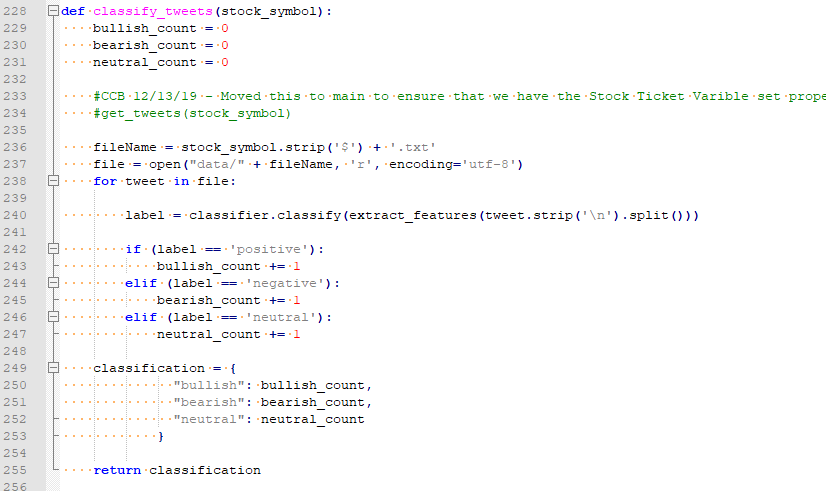
Once the training data has been processed and the estimated accuracy is acceptable, you can use iterate through the analysis data to create your sentiment analysis. In our example, we step through each Twitter post and attempt to determine if the post was Positive / Negative / Neutral. Depending on the classification of the post, the corresponding counter is incremented. After all posts have been processed, the category with the highest total is our sentiment indicator.

Generate Analysis

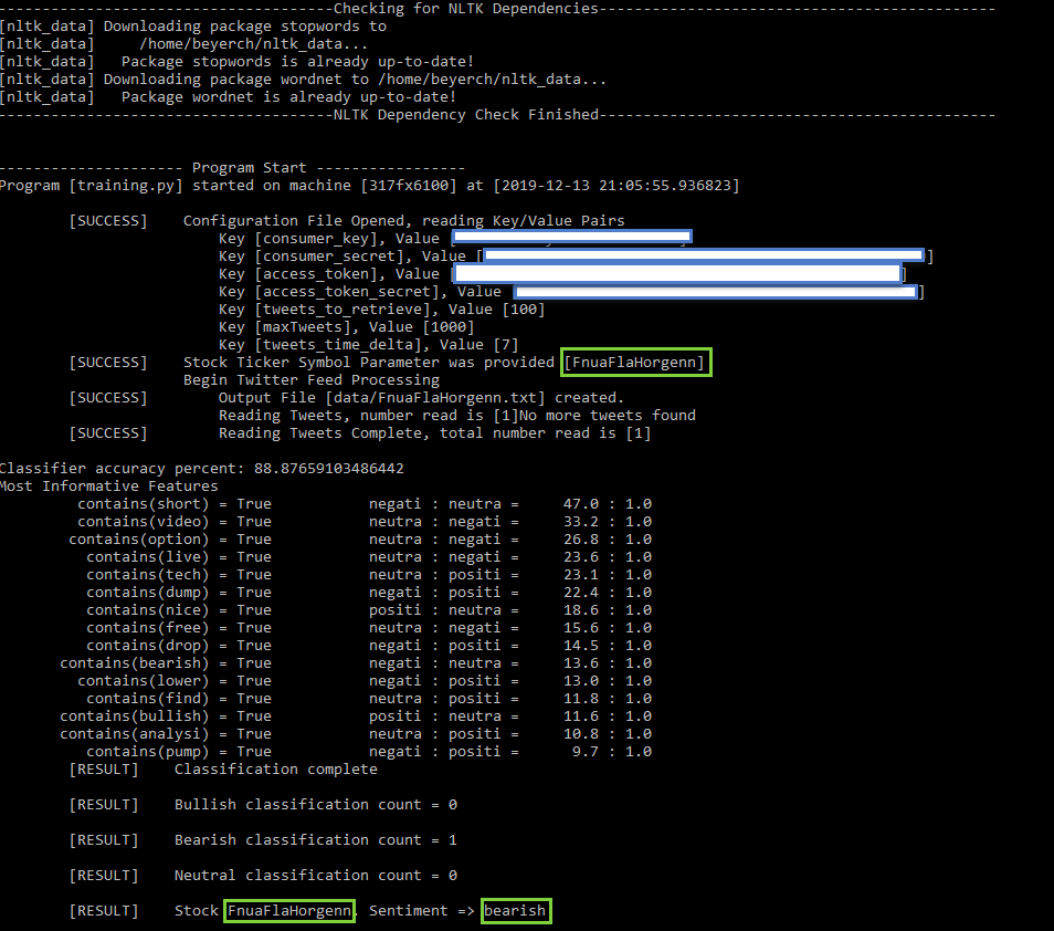
Once all of the pieces are in-place, you can run your process and review the output to validate your model. To simplify the testing, I created a fictitious phrase [FnuaFlaHorgenn] and created a handful of Twitter posts referencing it. I then ran the program to verify that it correctly classified the Twitter post(s)

H:\OneDrive\Illinois-Masters\CS410\410_Sentiment_Analysis - Copy\doc\images\FnuaFlaHorgenn_BadTweet.png

Figure 9 – Sample Twitter Post

Figure 10 – Twitter API Extract
H:\OneDrive\Illinois-Masters\CS410\410_Sentiment_Analysis - Copy\doc\images\FnuaFlaHorgenn_Bearish_Results.png

Figure 11 – Program Output (Bearish)

Conclusion

While NLP is not perfect and has limits, there are a wide variety of use cases where it can be applied with success. The availability of frameworks, such as NLTK, make implementation relatively easy; however, great care must be taken to ensure that you get meaningful results.