Overview
When reverse engineering an important, and rather fun, step is disassembly. Digging into the internals of hardware & software typically provides many clues as to how you can exploit a system. If you know what technologies are being utilized, this will make it easier to understand how the product works and how to exploit it. Additionally, by knowing what key components / technologies are in use will give you a starting point for finding attack vectors. (E.g. known vulnerabilities) Additionally, in many cases, an analysis of the hardware will result in the discovery of diagnostic/debug access to the system. This is especially true for the Tesla Media Control Unit (MCU)
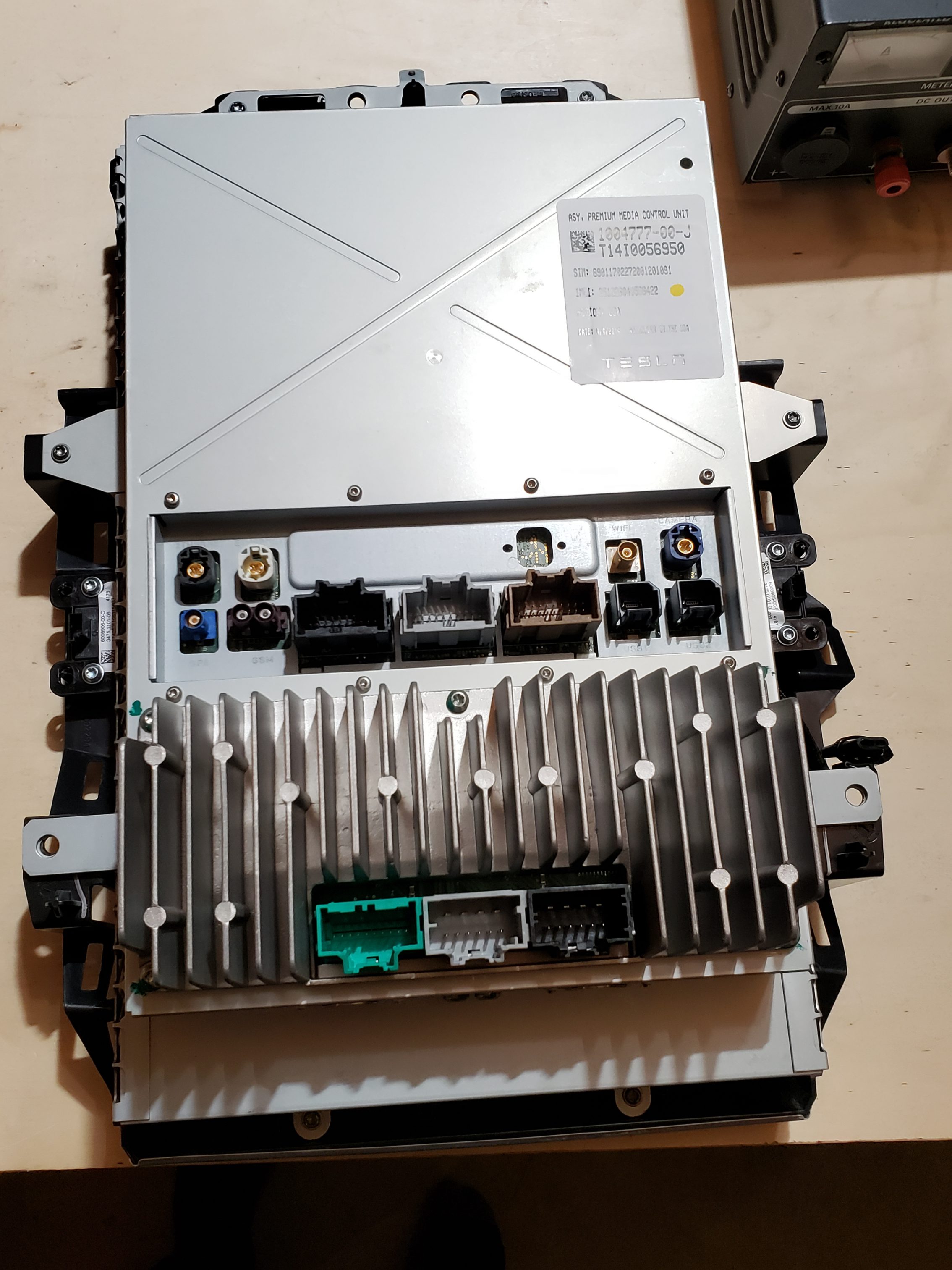
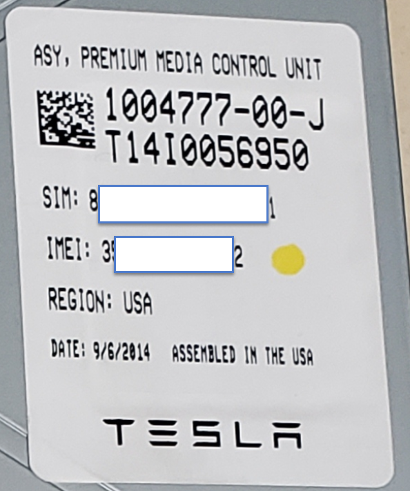
The MCU, which has numerous implementations, is a complex device which is critical to the operation of the Tesla vehicle. The MCU serves as the primary user interface for vehicle control/configuration, navigation, radio, entertainment, communication & coordination w/ other vehicle modules, diagnostics, and remote communication w/ Tesla HQ. Given the complexity of this unit, any/all clues to its operation will be extremely helpful in understanding how it operates. A full tear down & inventory of key components is ONE method to increase our knowledge.
The MCU consists of the key sub-assemblies:
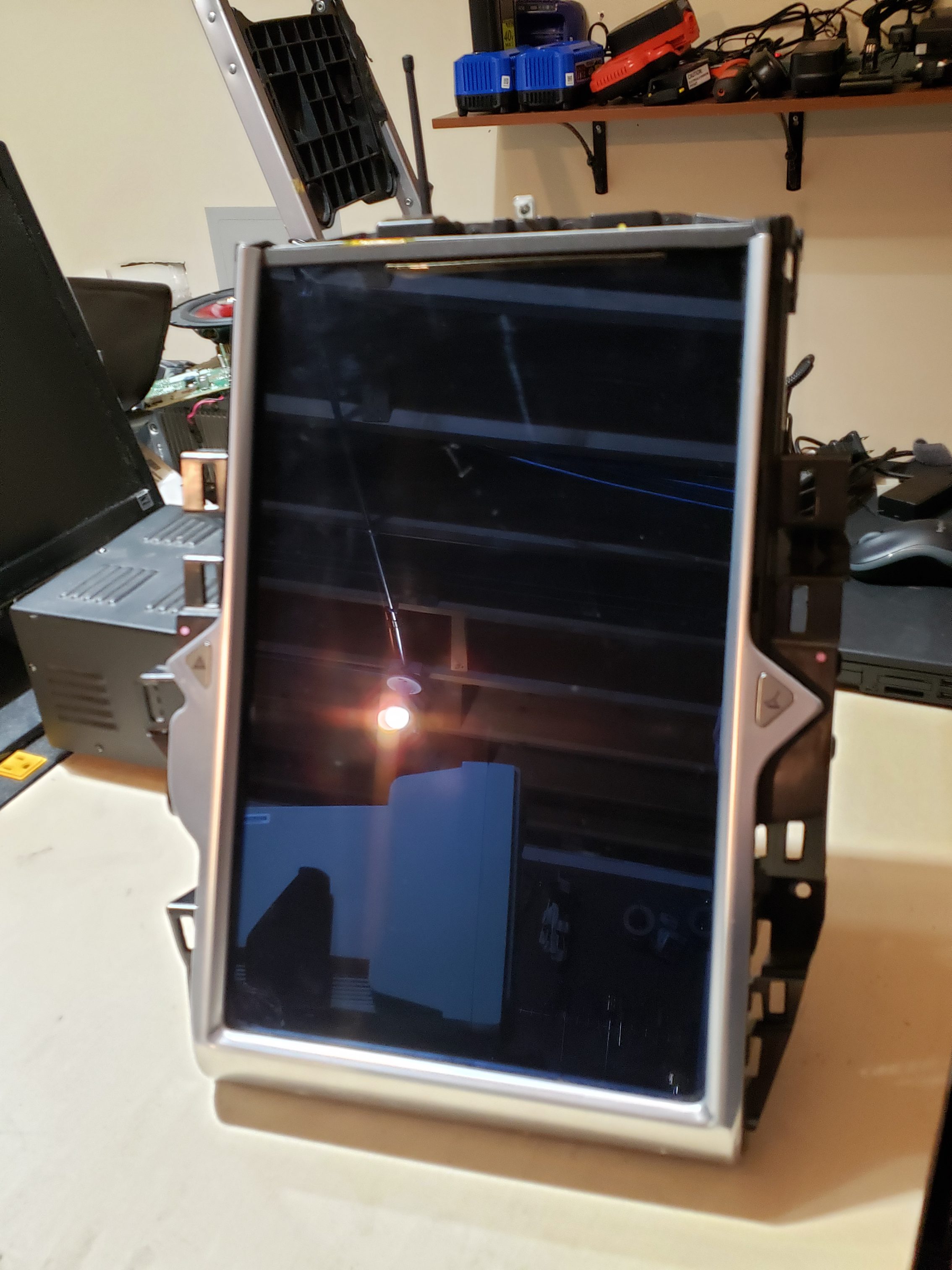
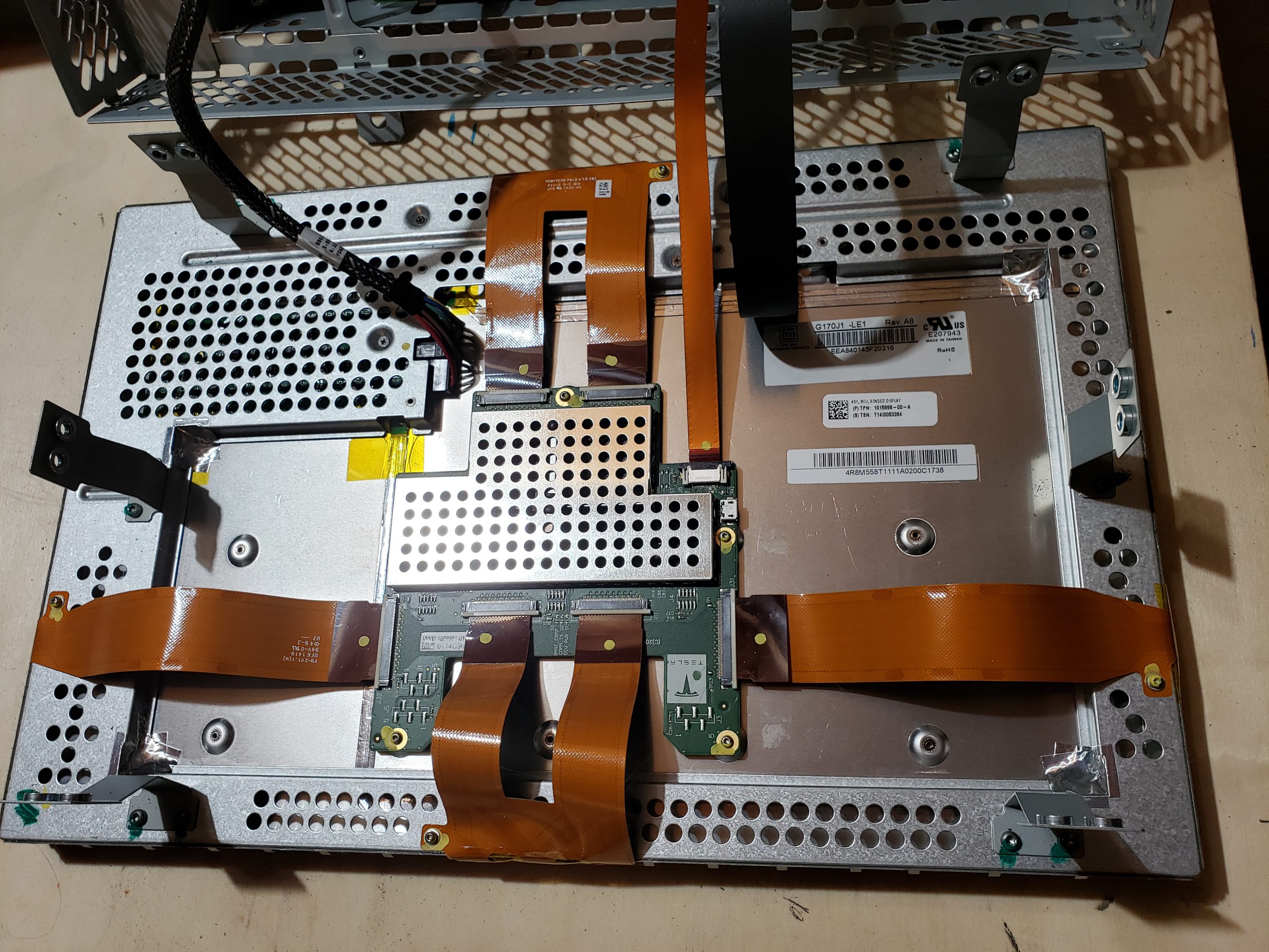
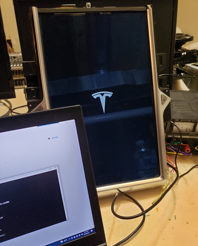
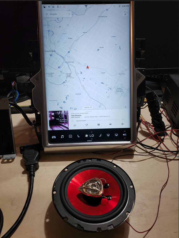
- Bonded Display – For most people, this is the only assembly that matters as it collects user input and provides visual feedback.
- Amplifier Assembly – Audio amplifier module which drives speakers, etc.
- Cellular Communications – This sub-assembly is responsible for cellular communications. Early MCUs supported 3G while newer sub-assemblies support 4G/5G.
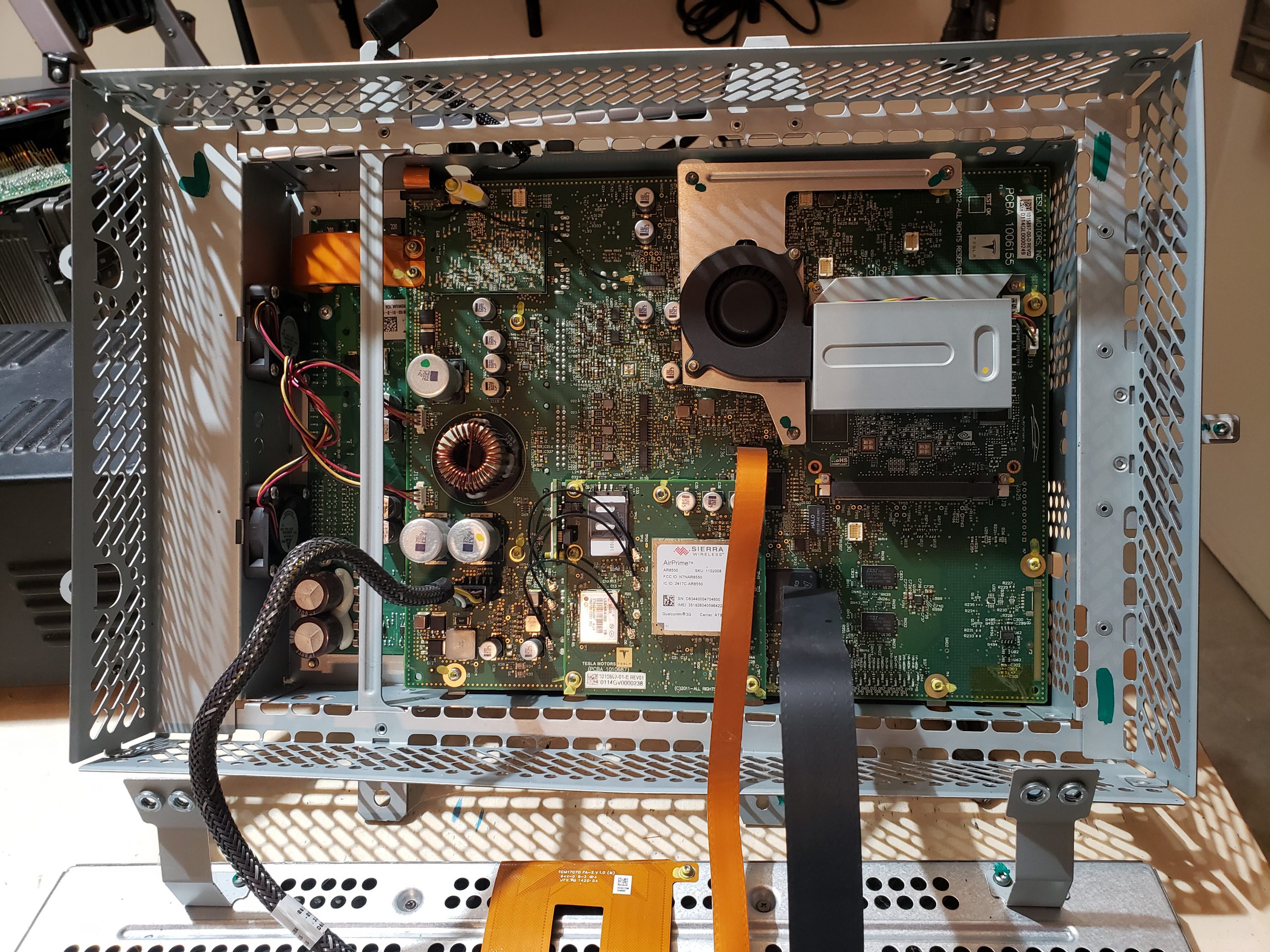
- Infotainment Processor – This sub-assembly provides the main processing power for the MCU. For the MCU 1, this is powered by NVidia while MCU 2 utilizes Intel Atom, and MCU 3 contains an AMD Ryzen processor.
- Main Board – This is the largest assembly and serves as the hub for all of the other sub-assemblies.
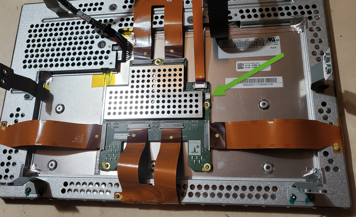
Bonded Display
From a reverse engineering perspective, this is probably the least interesting sub-assembly. The electronics are relatively minimal and single purposed. I don’t expect there to be much value in focusing on this assembly. With that said, there is a USB port on the control board. I suspect this is probably used for pushing firmware in the factory.
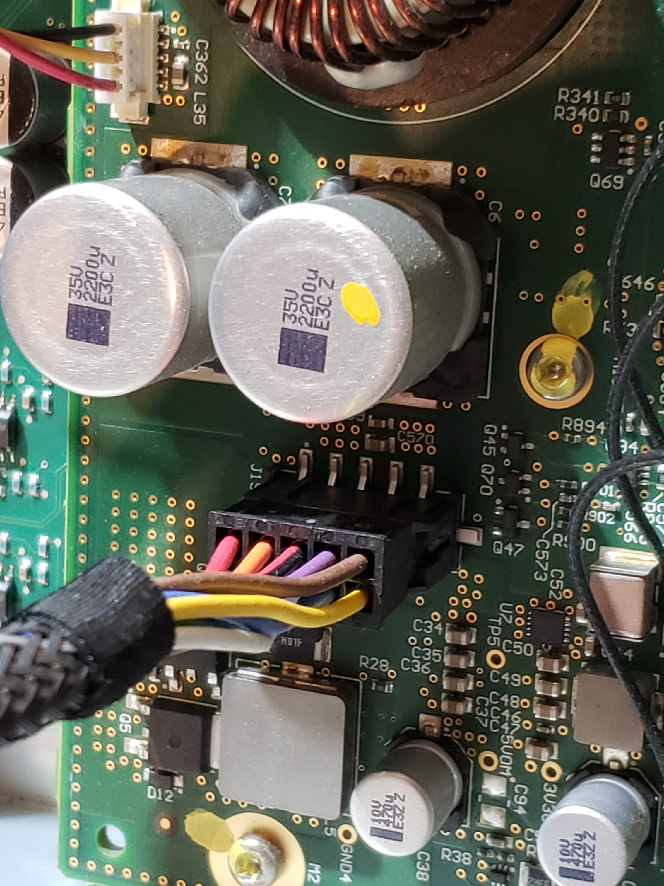
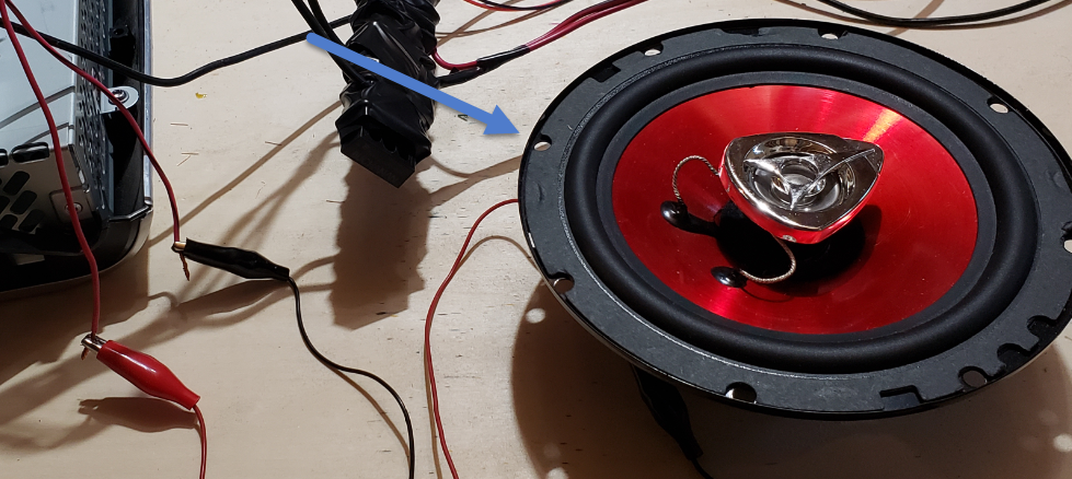
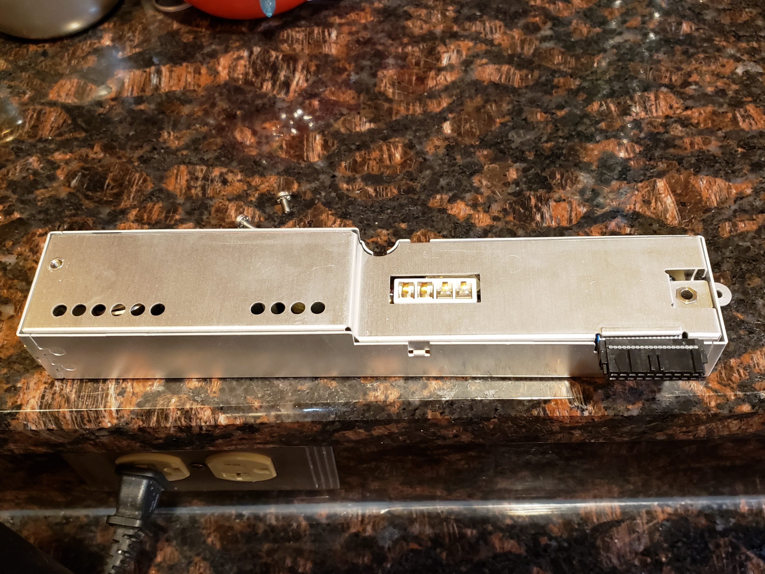
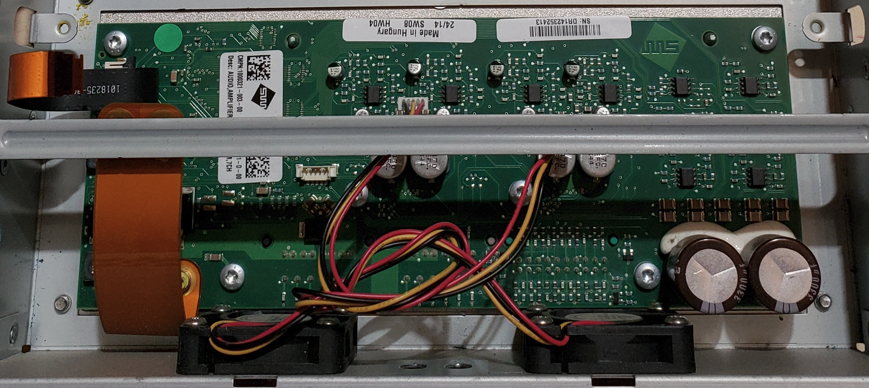
Amplifier Assembly
Similar to the display, this assembly is also very single purposed and I don’t see any obvious value in focusing too much time here. A quick review of the circuit board does not find anything remarkably useful for reverse engineering purposes.
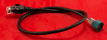
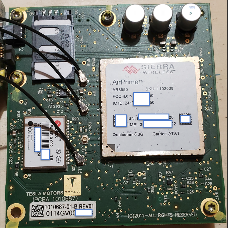
Cellular Communications
This module is far more interesting as it is responsible for remote communication, which is quite valuable. There are multiple prominently displayed components on this board of note. Additionally, you’ll see that this contains a removable SIM card. As the older modules came with “unlimited data”, perhaps you can repurpose this? ☺ It would additionally be curious to see if any data is on this card.

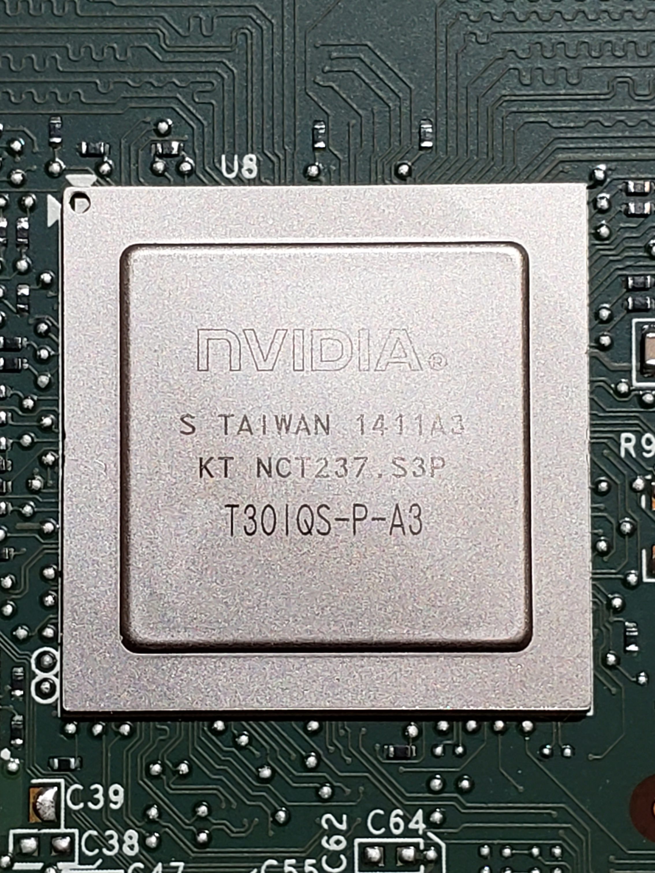
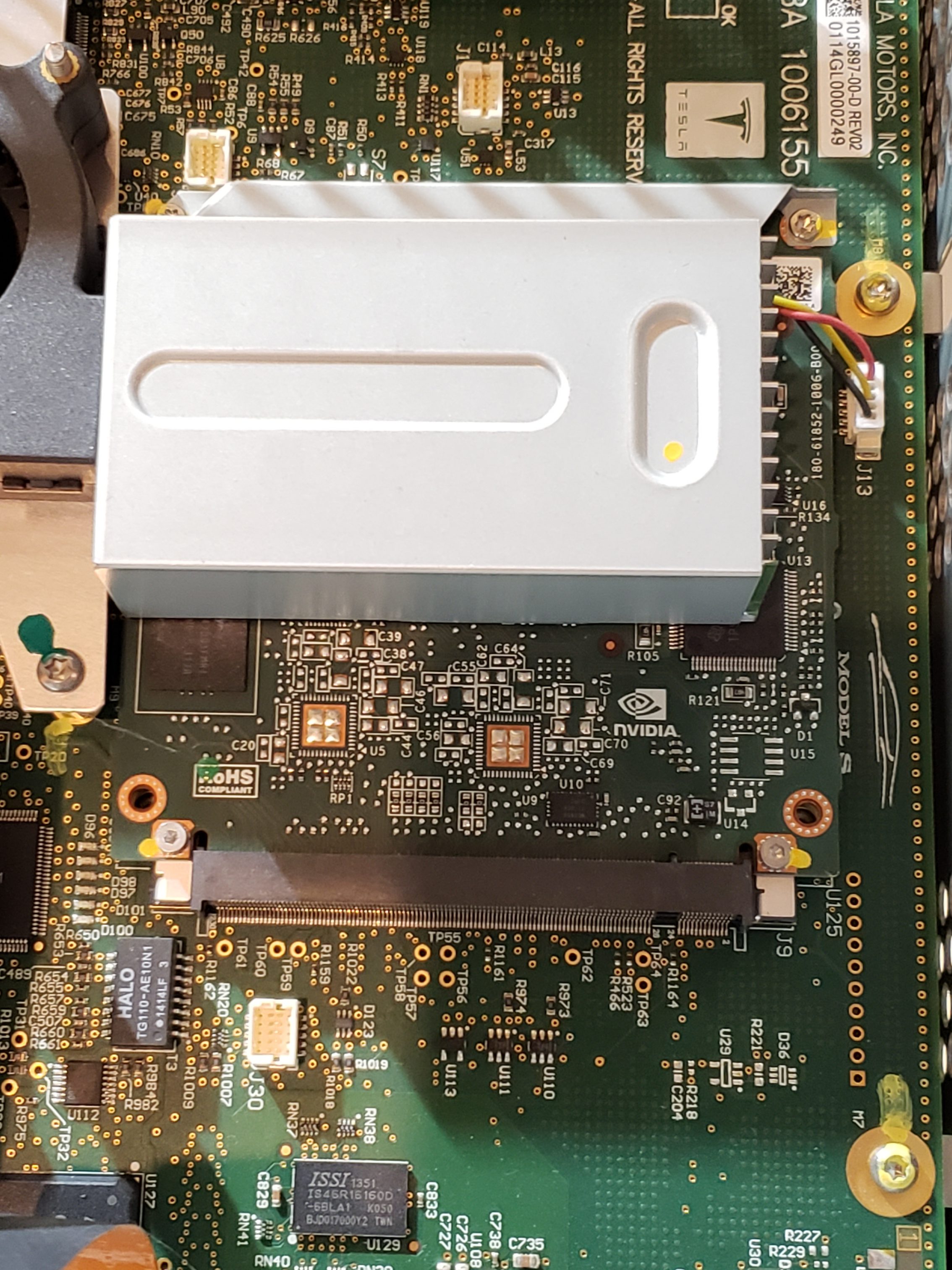
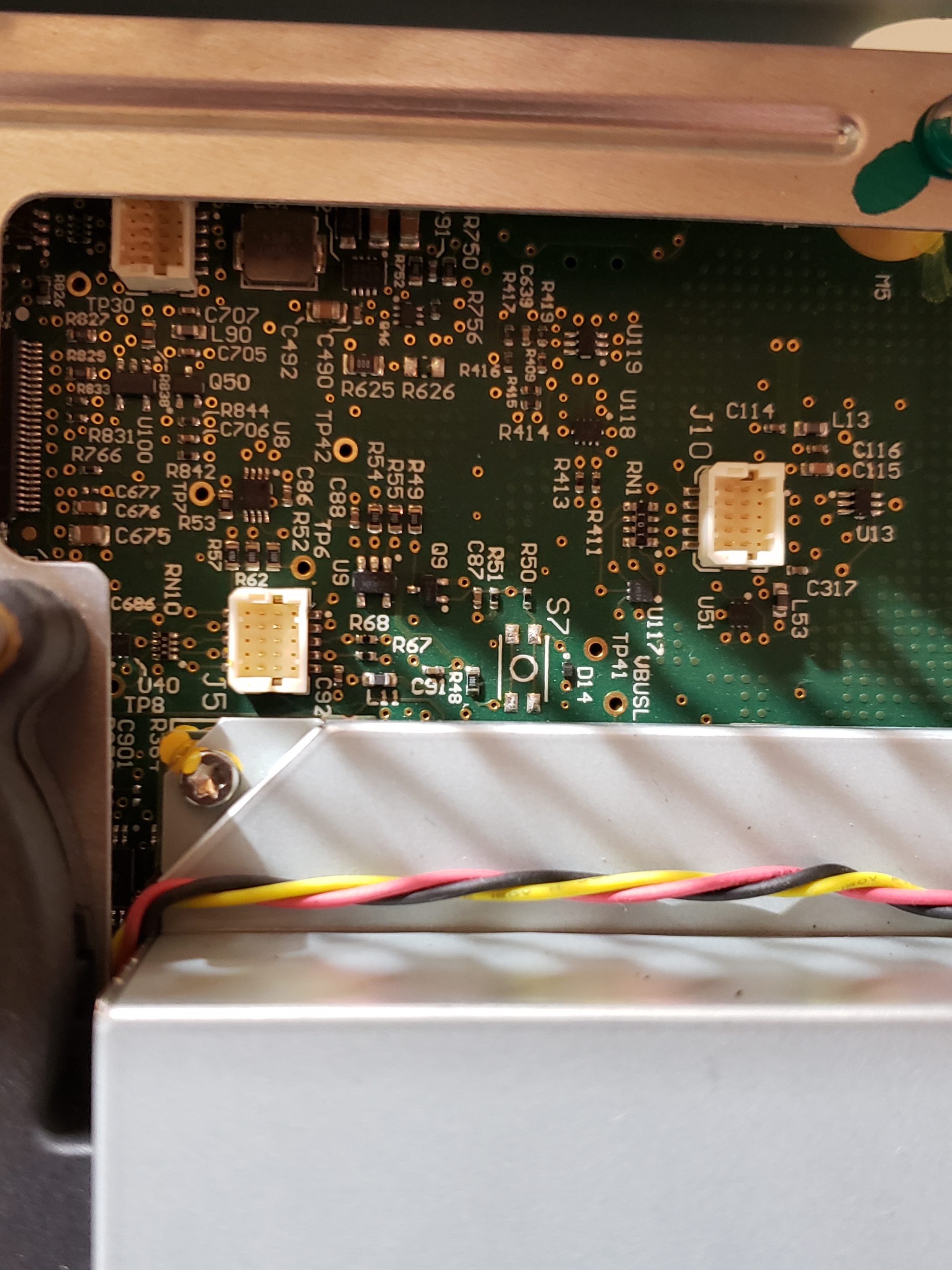
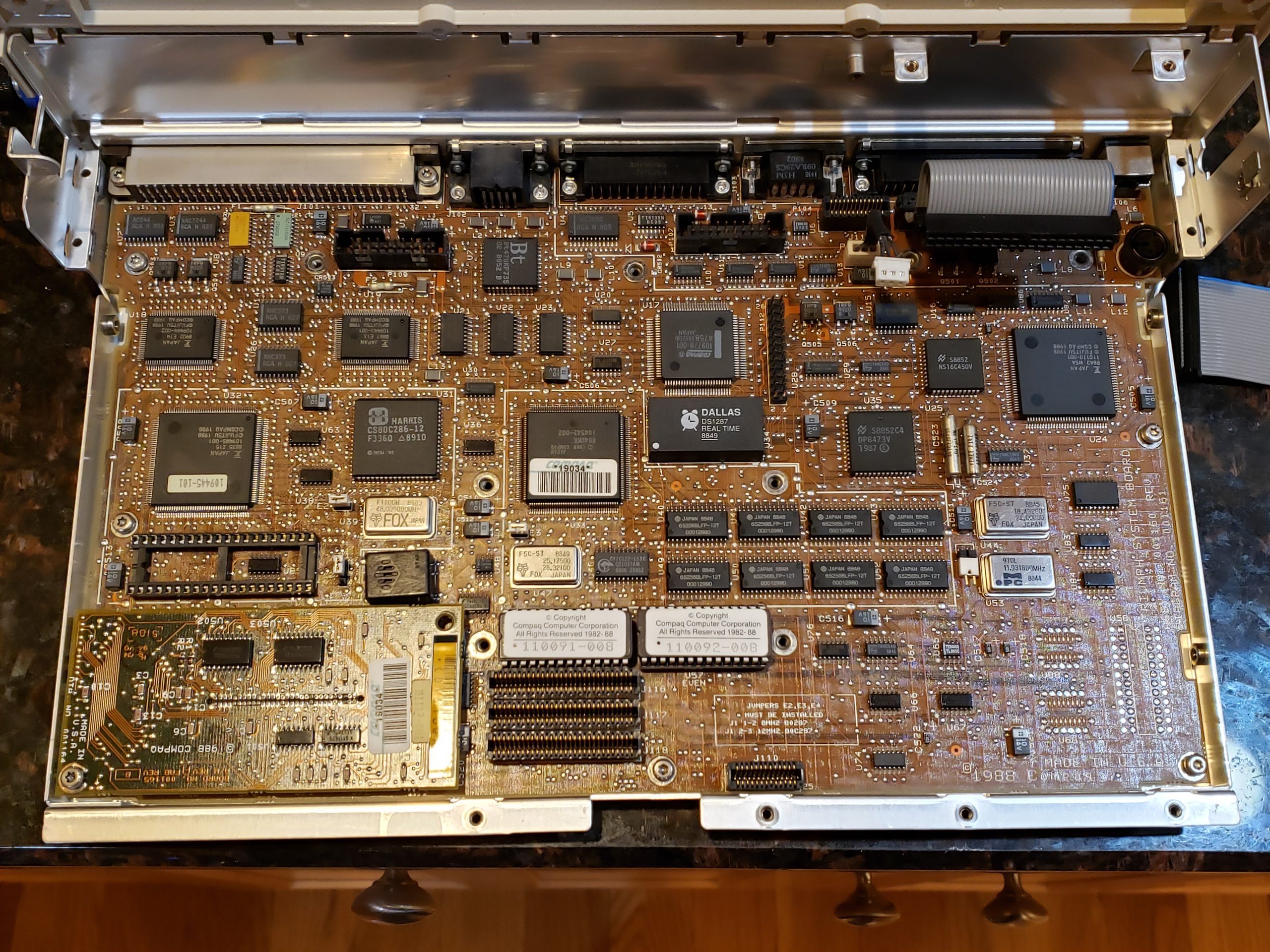
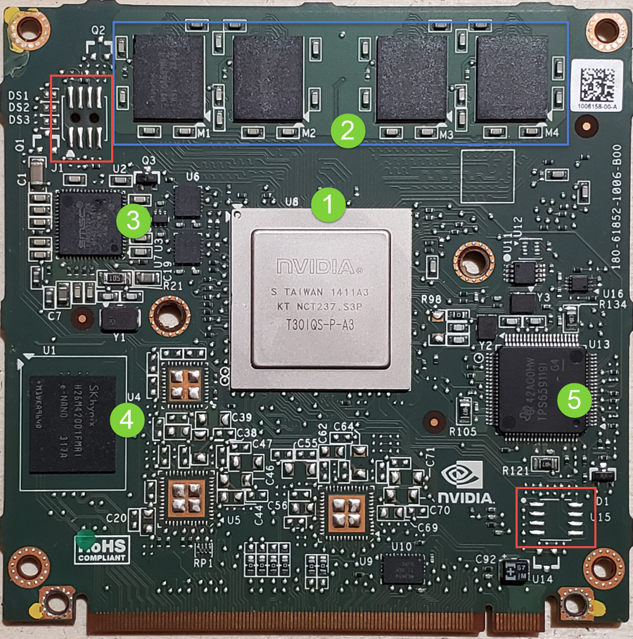
Infotainment Processor
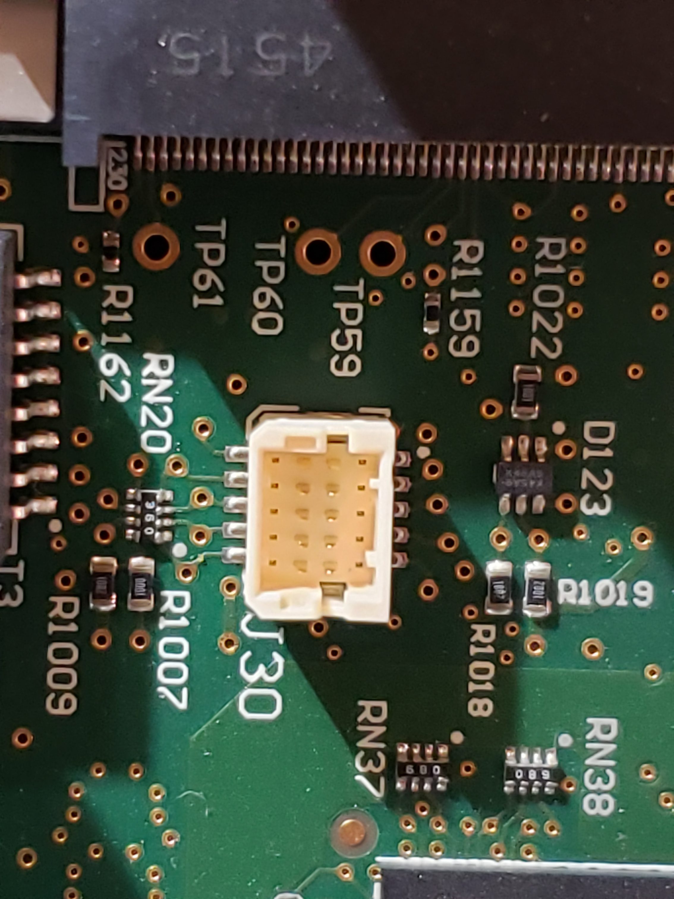
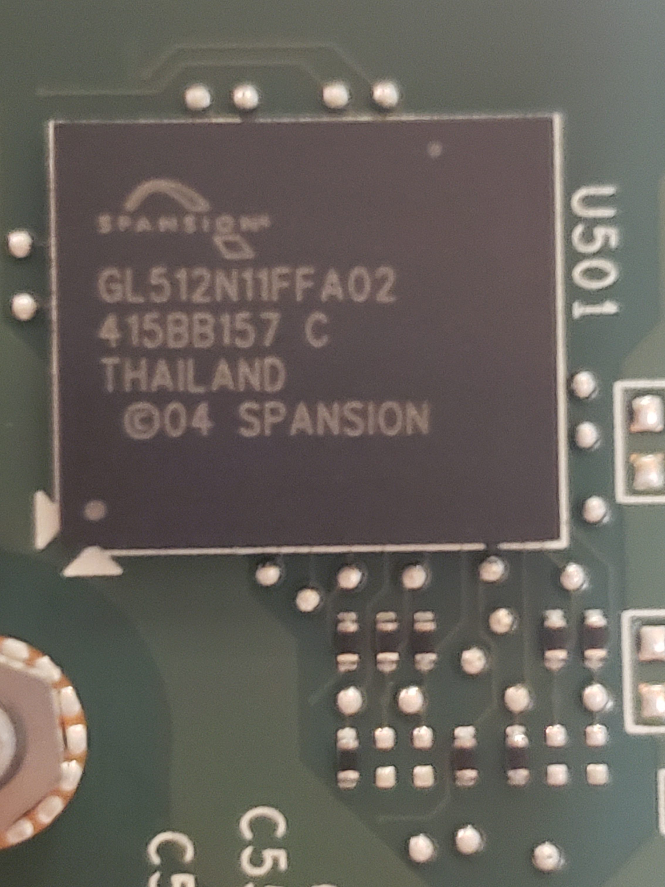
The infotainment process assembly is another “high value target” as this is the primary “brains” of the MCU. In addition to the NVIDIA processor, this board contains SDRAM, e-NAND Flash Drive*, a USB Hub, Ethernet controller, and an IC flash device. In additional to the components, on the board, there are a couple of unpopulated pads. Perhaps these pads are simply for optional components or perhaps they are for diagnostic purposes. More investigation is required to determine if they are of any value. 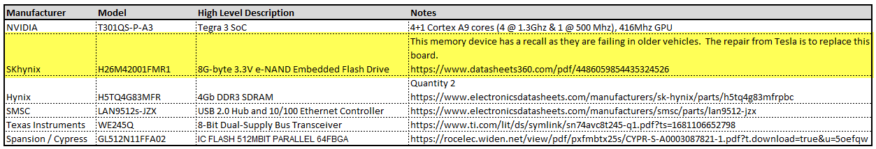
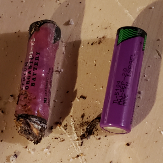
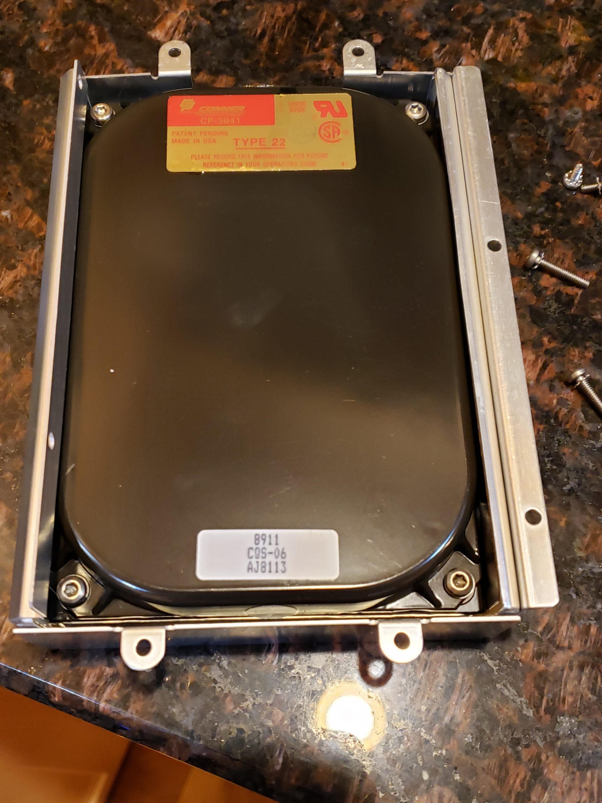
* – Due to how the Flash Drive has been utilized by Tesla, these devices are beginning to fail in older MCU 1 vehicles. When they fail, the MCU will operate erratically eventually resulting in the “black screen of death”. There is a recall and Tesla will replace these sub-assemblies with a newer/higher capacity flash memory. If you are skilled, you can repair this yourself. ☺
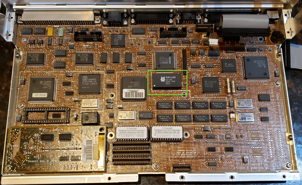
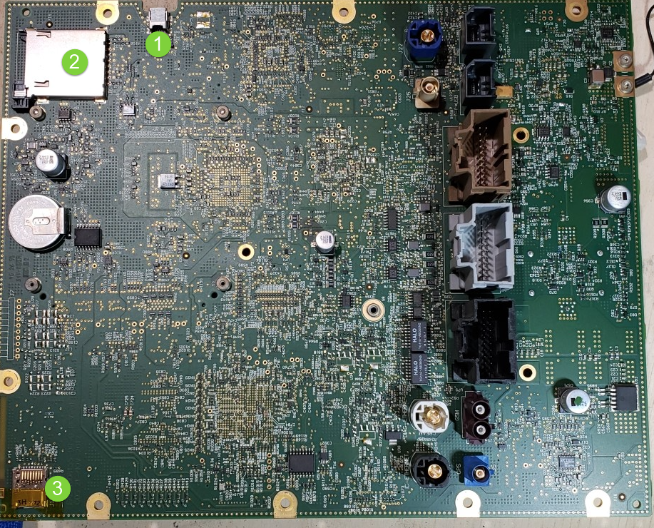
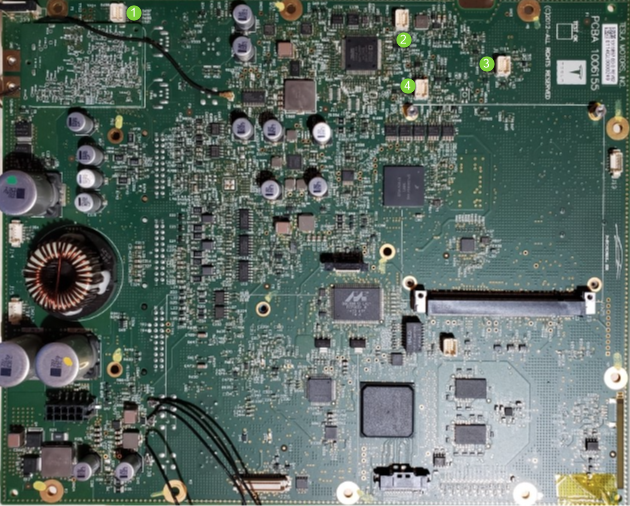
Main Board
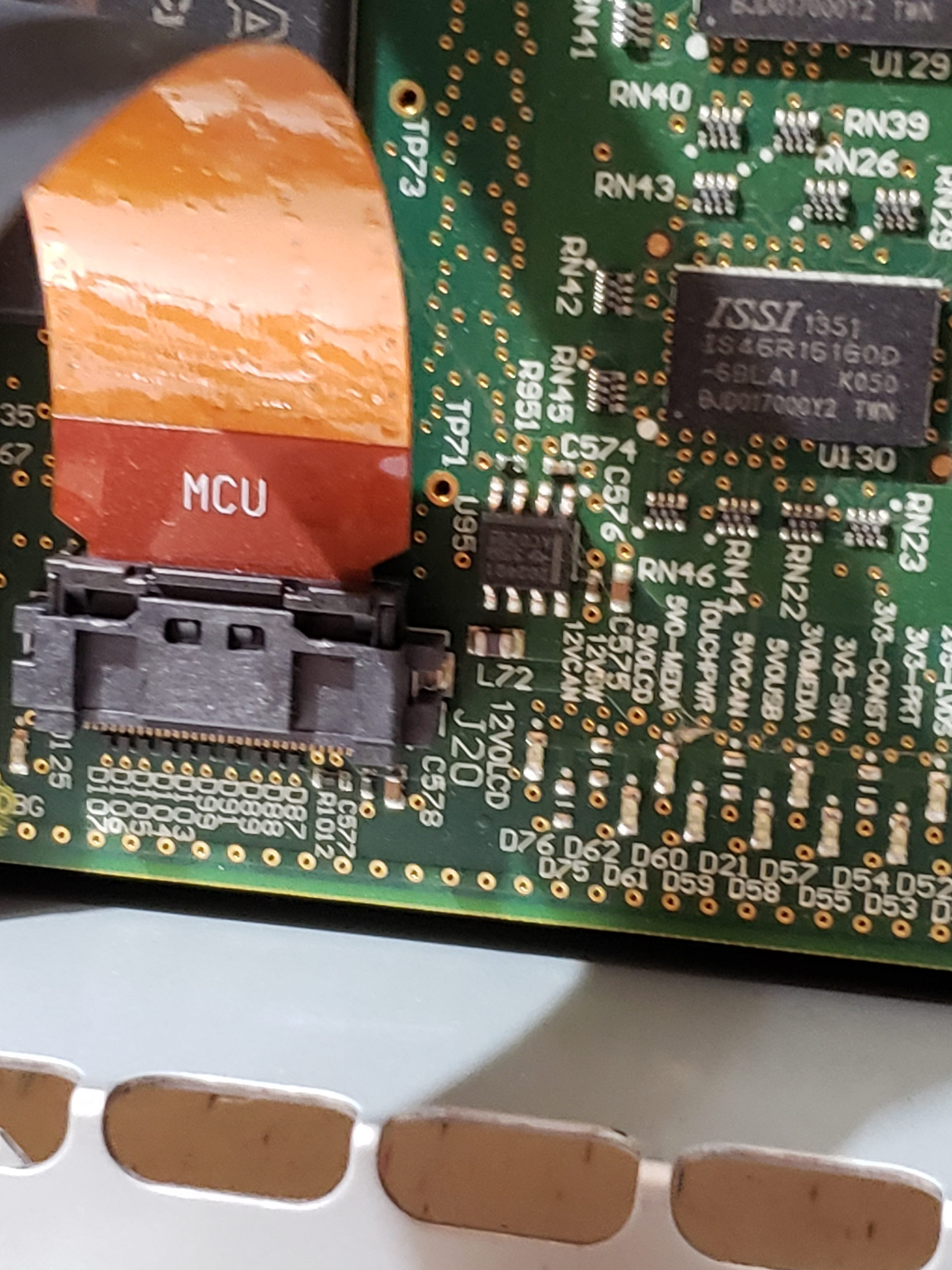
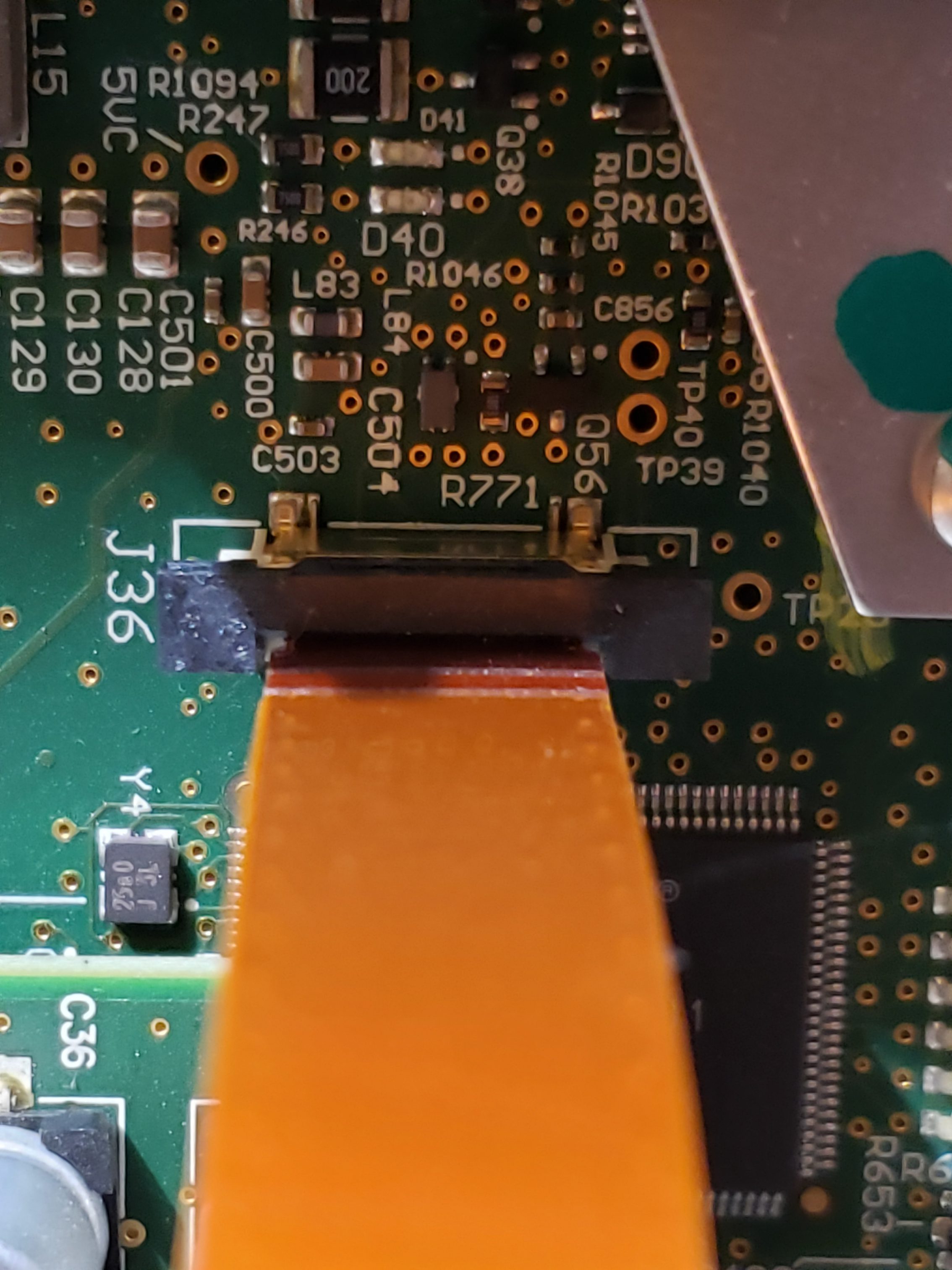
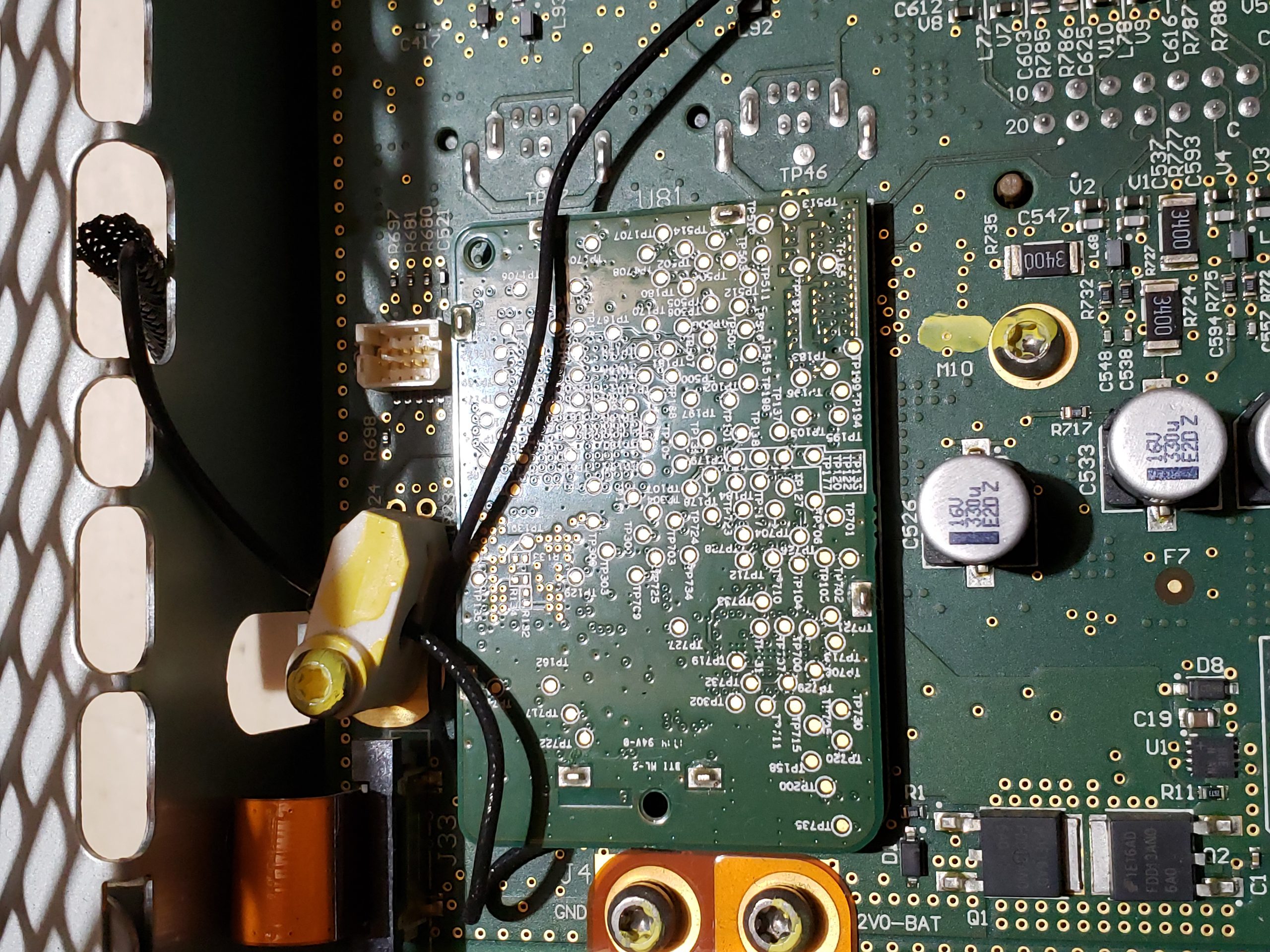
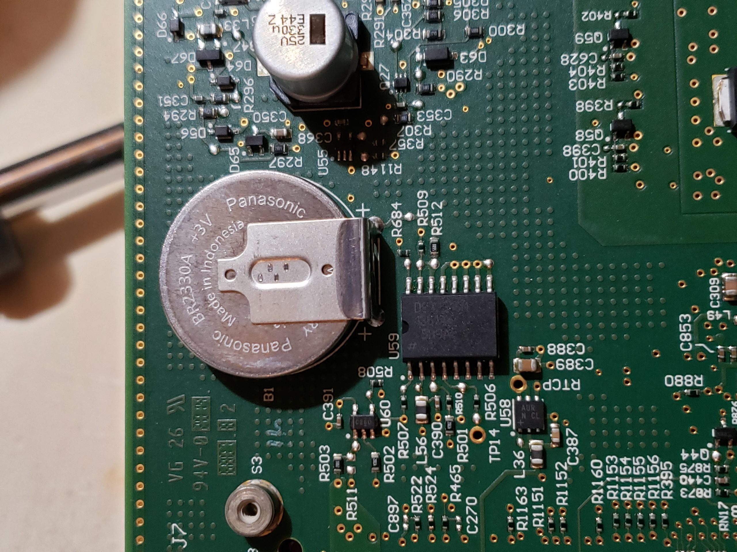
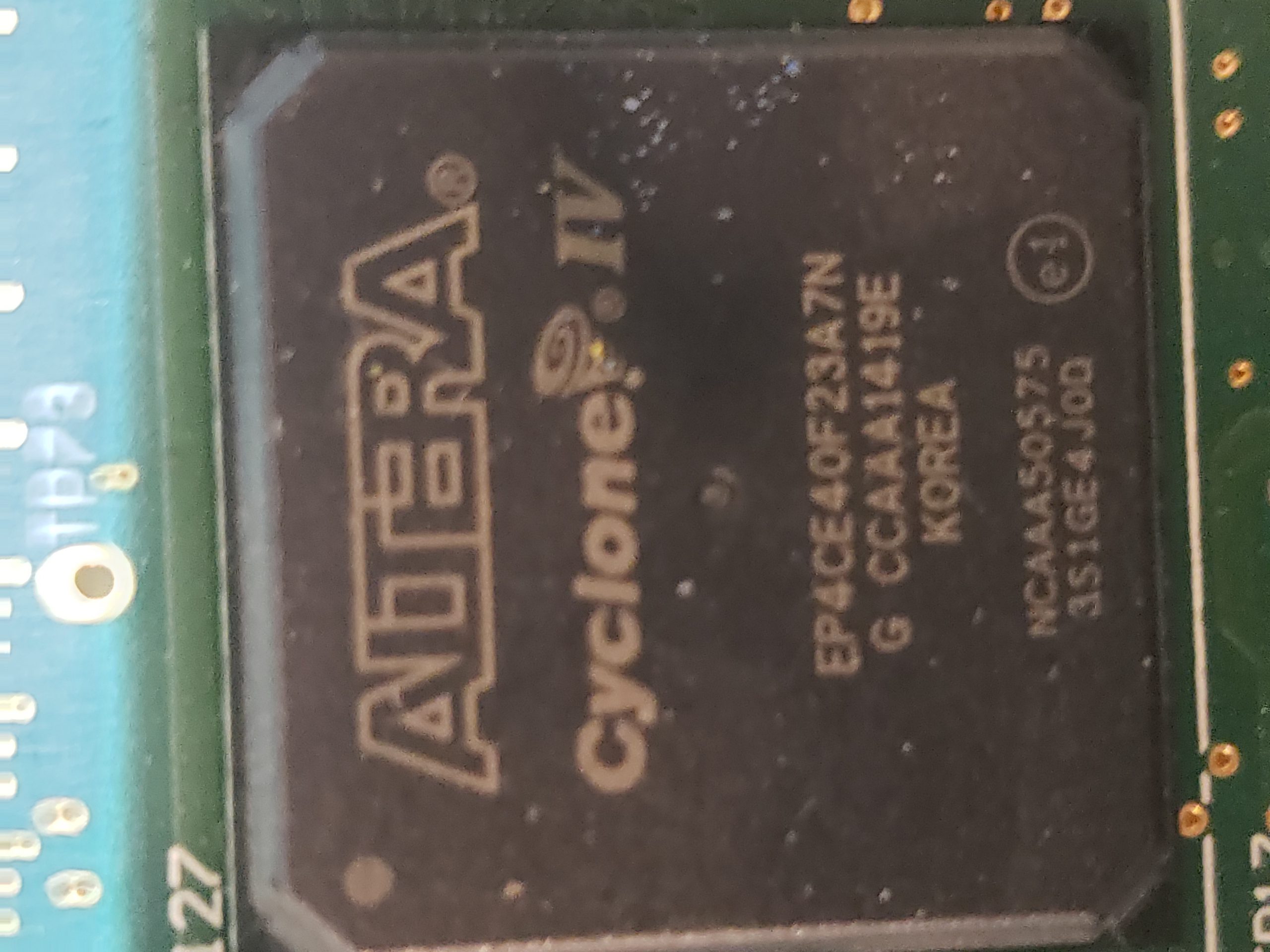
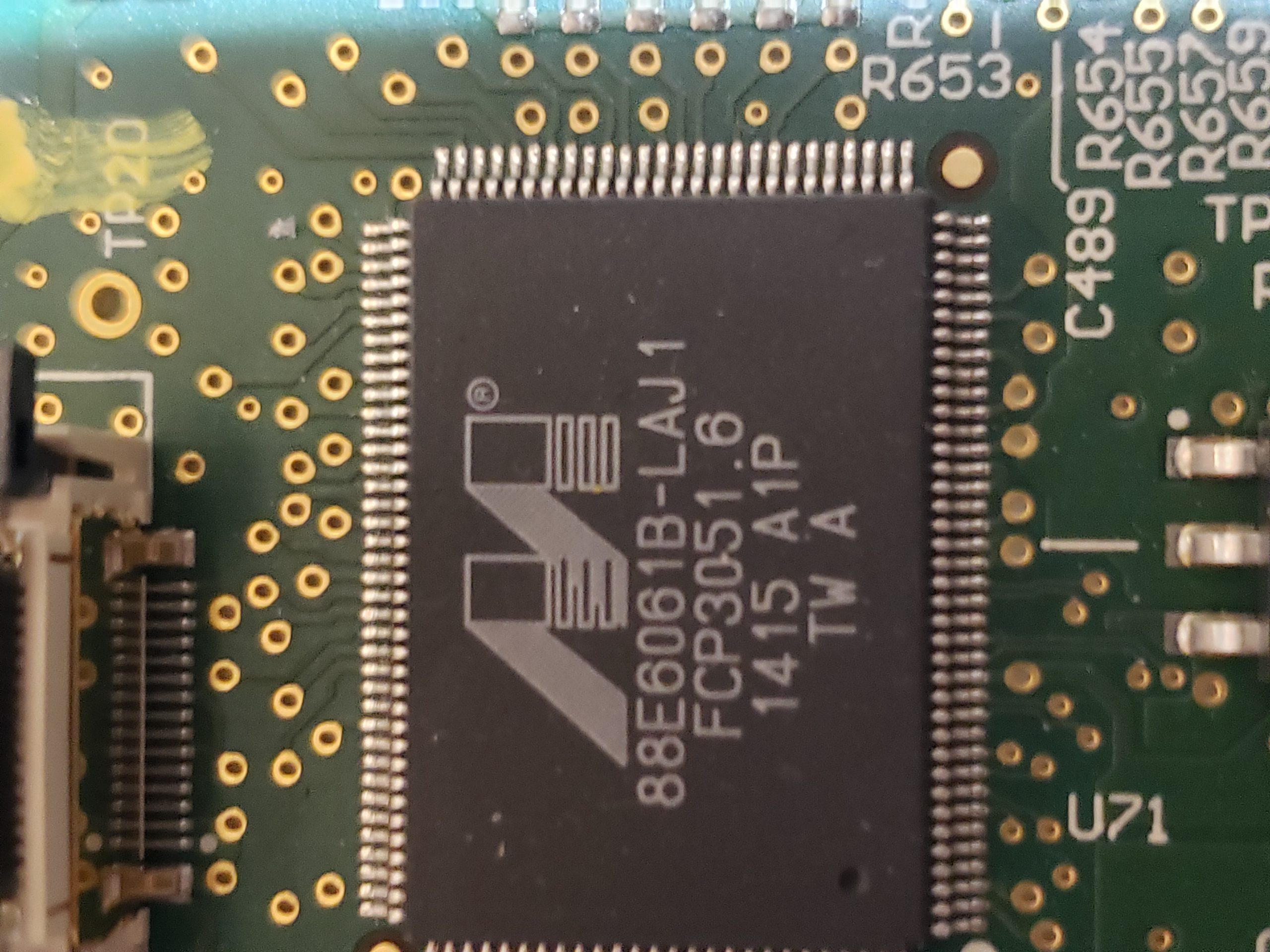
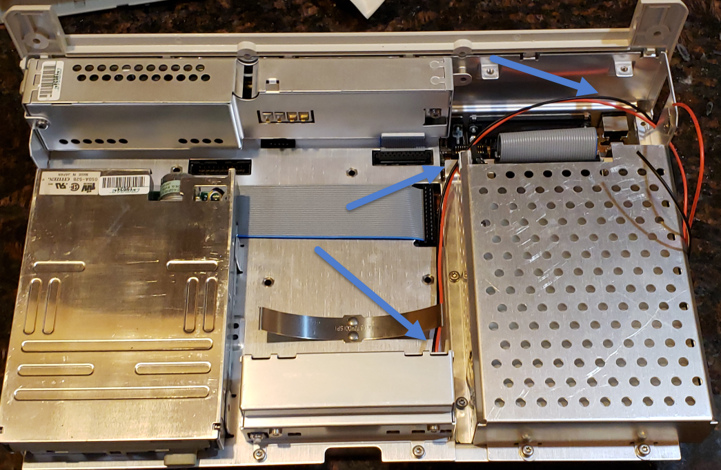
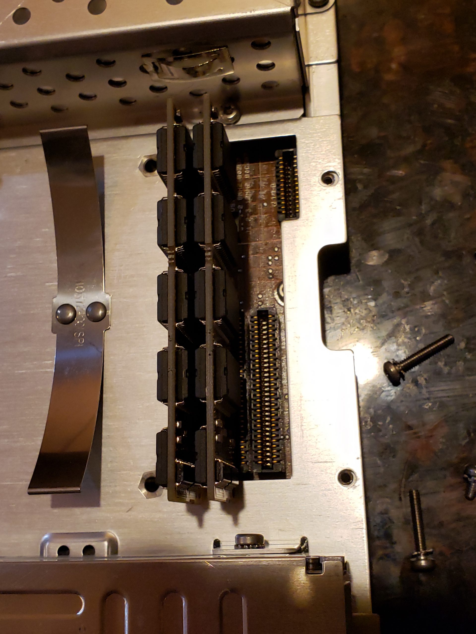
Given the size of the main board, it shouldn’t be surprising that there are many components of interest here. On this board, there are numerous communications chips: Switched gigabit Ethernet, multi-media serial links, CAN, and LIN. As I know the MCU plays “gatekeeper” for both Ethernet and CAN communications, reviewing these components for weaknesses will be a high priority.
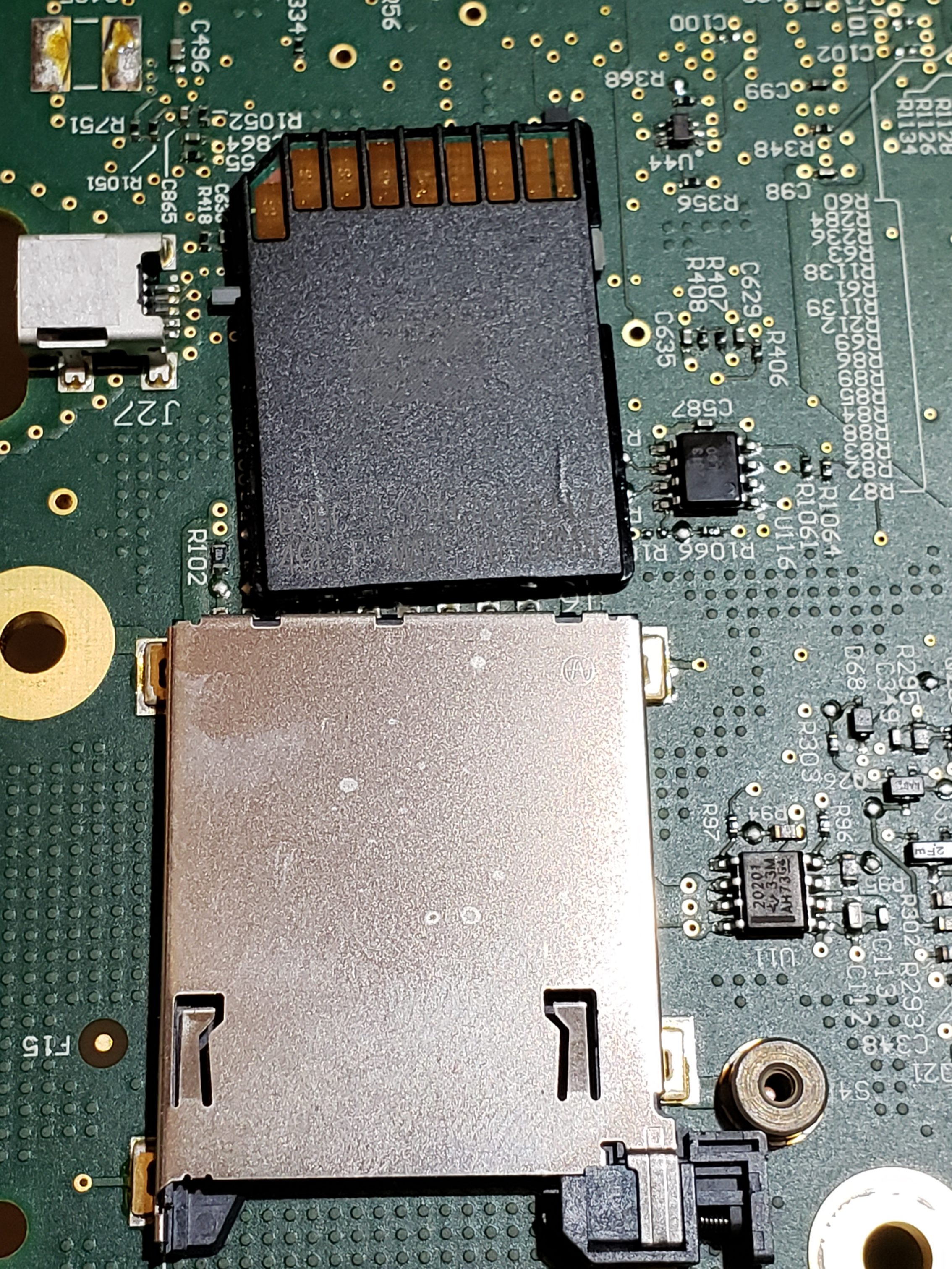
Aside from the communication ICs, this board also contains Micro SD & SD data cards, a hidden USB port, and multiple JTAG/TI diagnostic connectors. While I’m not going to “spill the beans” (yet) on the contents of the data cards, I will say there are both very useful for reverse engineering purposes. I will point out that NEITHER card is automotive/harsh environment grade. Because of this, they will fail much sooner due to the temperature extremes in a vehicle. If either of these cards fail, you are in for a very bad time!
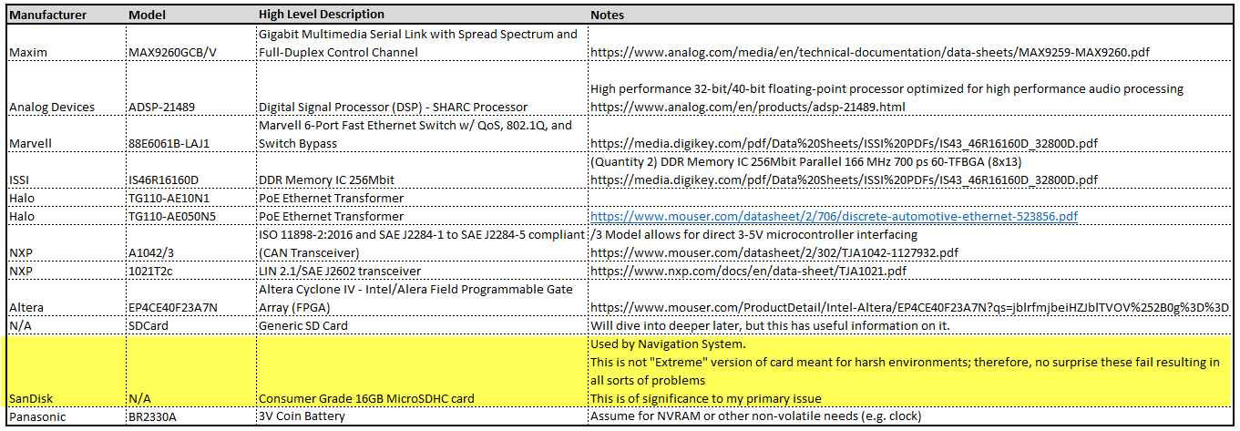
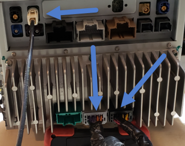
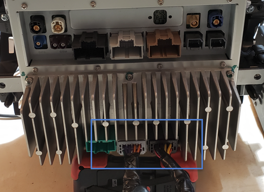
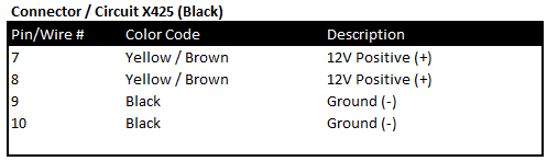
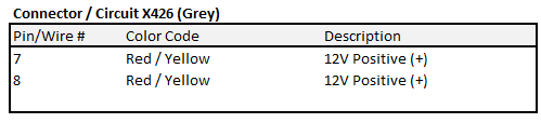
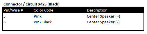
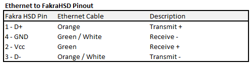
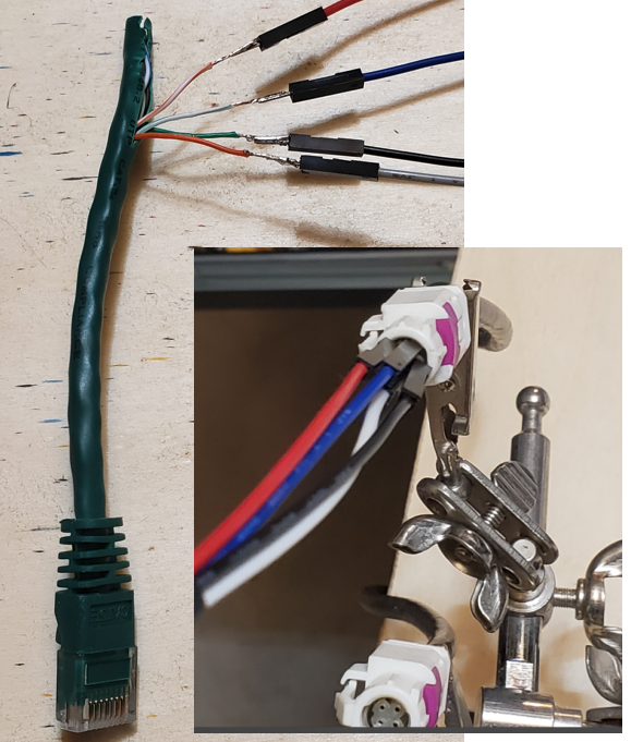
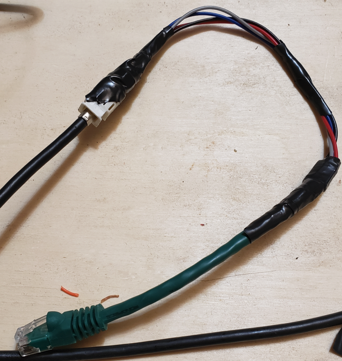
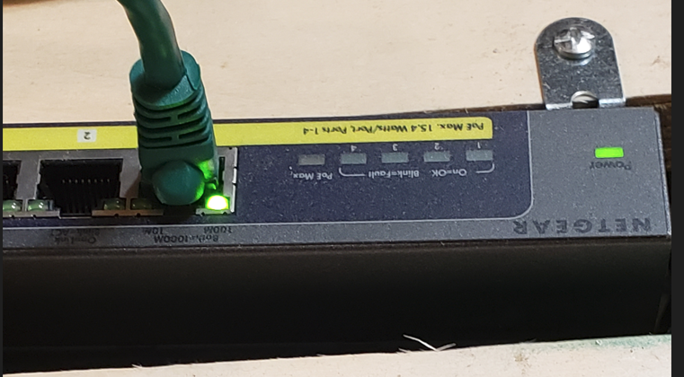
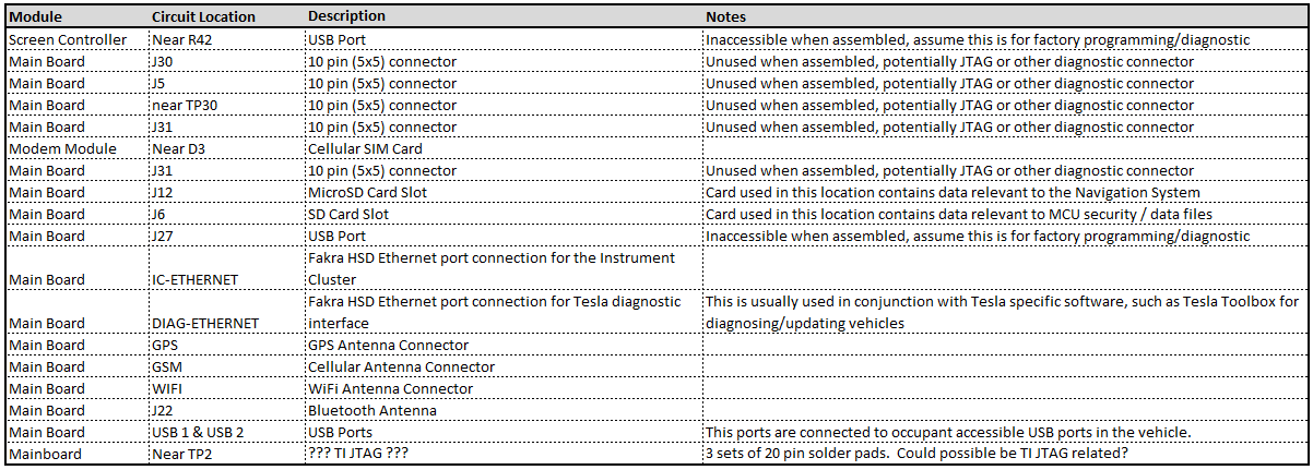
“Ports of Interest”
As noted in the sections above, there are some connection points of interest. The following tables is a consolidated list for reference.
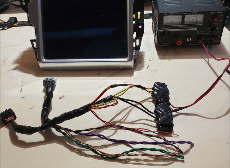
Next Post: Navigation Repair
In the next installment, we’ll dig into my Navigation Issue and how the information learned during this disassembly allowed me to ultimately resolve the issue.