Browse Category

Misc. Technology

Tesla Reverse Engineering: Creating a Bench Setup (MCU)

Overview

After growing up surrounded by cars, I’ve grown accustomed to doing my own maintenance and repairs where possible. When I transitioned to EVs a couple years back, I expected that some repairs may require more manufacturer involvement than I was accustomed to. Unfortunately, due to Tesla being DIY Repair unfriendly, the situation was worse than I expected.

Even more unfortunate, the local service center has struggled to provide consistent quality service trapping me in between a rock and hard place. One prime example was when my 2014 Model S’ navigation stopped functioning properly. After almost nine months of back and forth & no resolution from Tesla, I decided that this would be a good opportunity to dig into the computer system to see if I could resolve the issue myself.

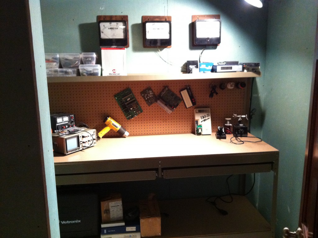
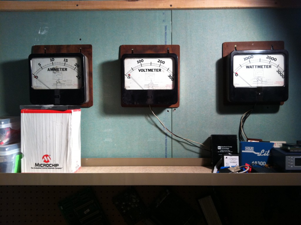
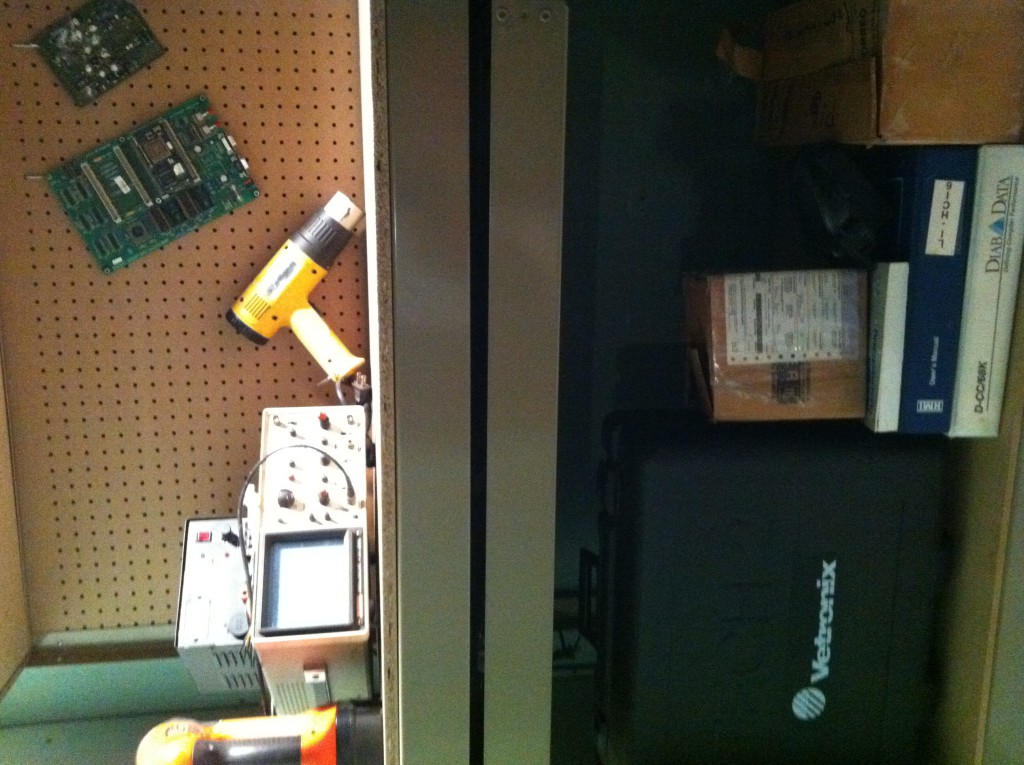
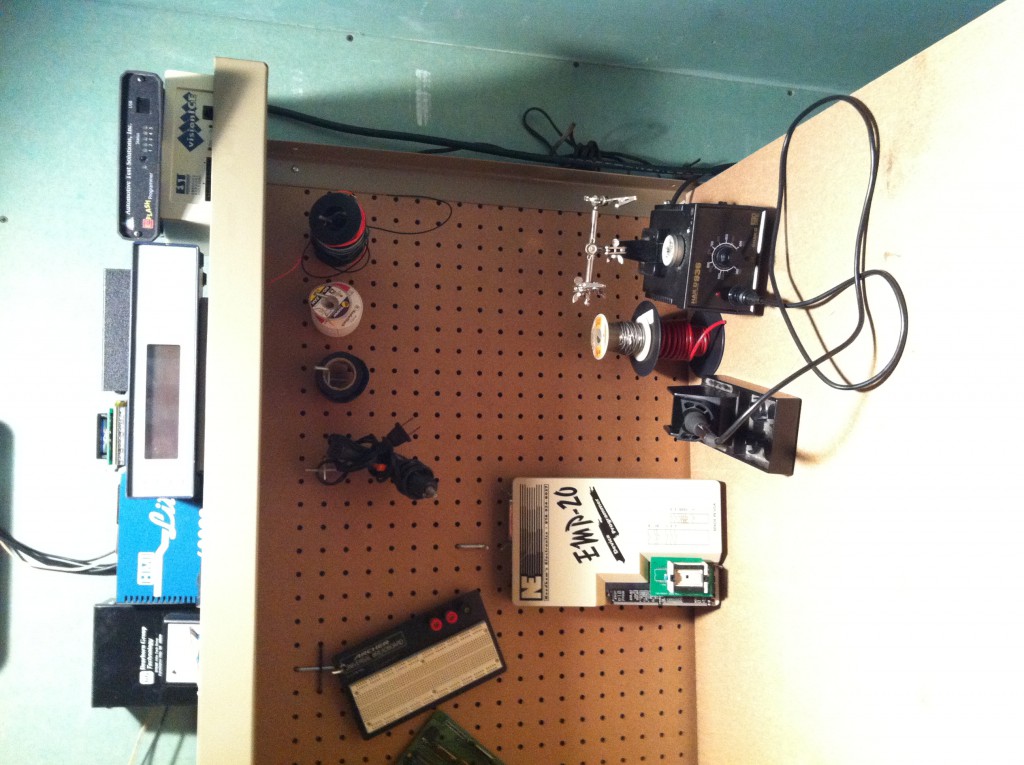
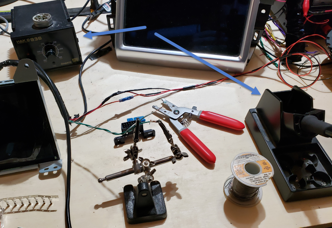
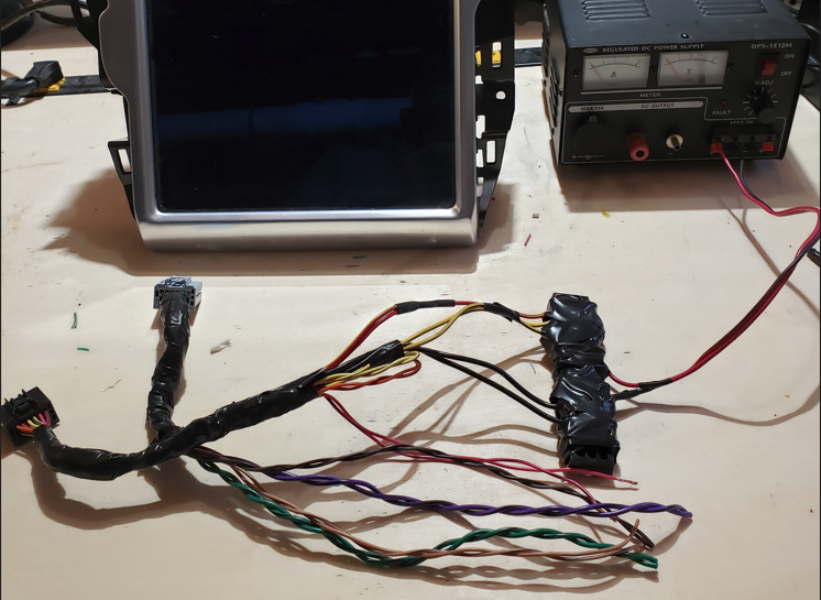
As I didn’t want to tear my car apart (yet) and I prefer to be comfortable while experimenting, my first order of business was to setup a test bench in my “mad scientist lair”. Having this would allow me to analyze the hardware and the physical & software interactions between the various modules used in the vehicle.

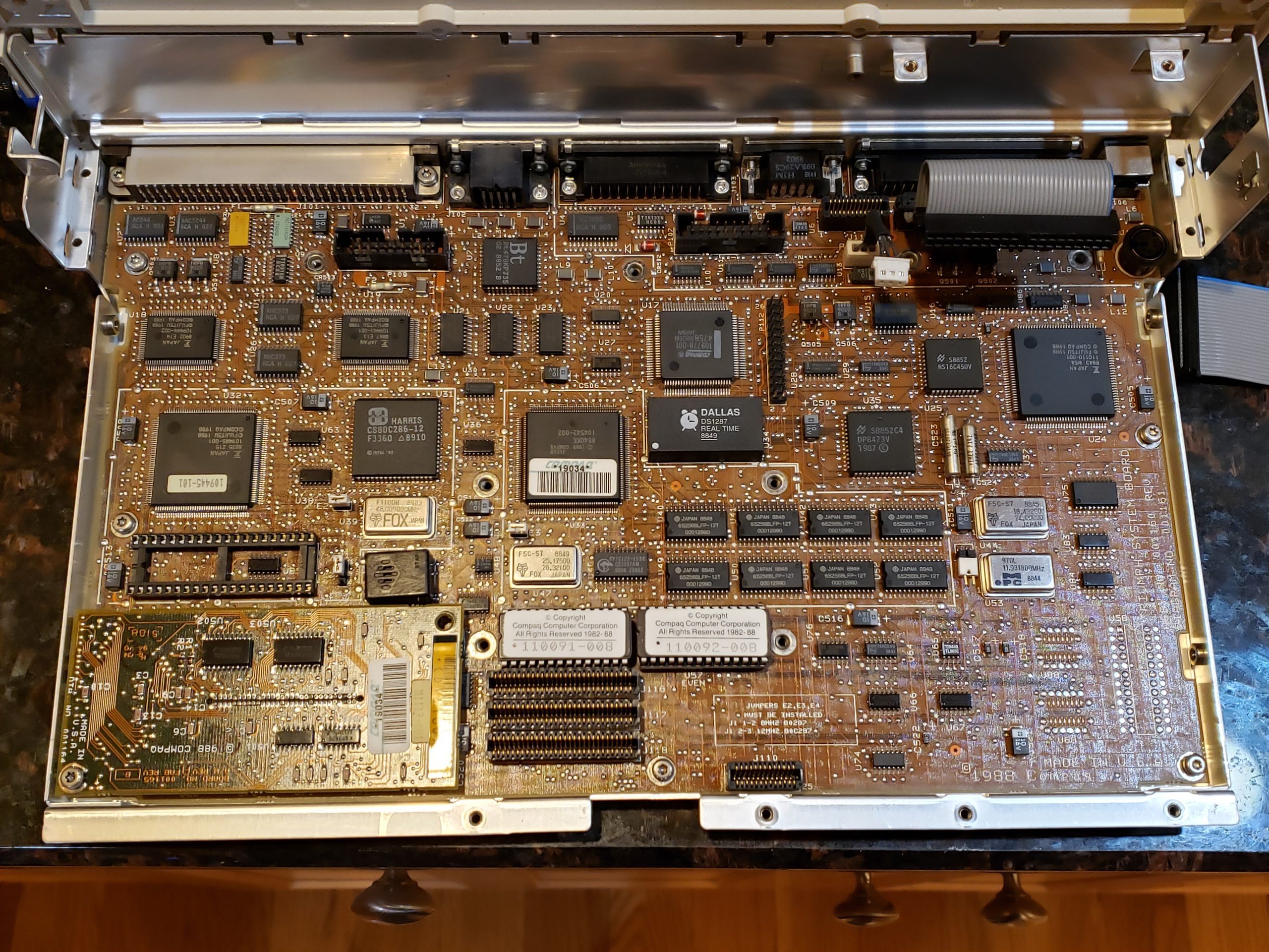
While there are numerous modules in the vehicle, my primary point of interest is the Media Control Unit. (MCU). The MCU is the main unit in the Model S and is the obvious analysis point for my navigation issue. The goal of this post will be to simply get the MCU up and running on your bench. In later posts, we’ll dive into more thoroughly analyzing it and other modules.

Step 1 – Getting Parts

In order to run the MCU on your test bench, we’re going to need a few things:

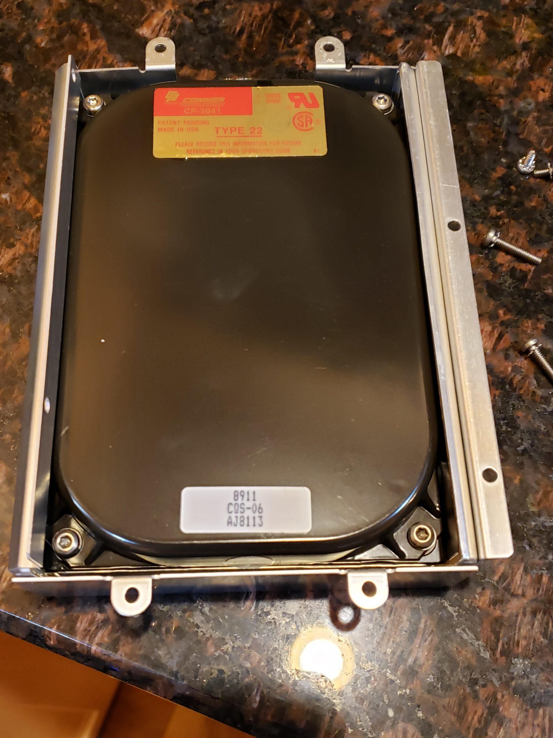
  • An MCU! As it is unlikely you will have a spare laying around, acquiring this will be first on your shopping list. Acquiring directly from Tesla isn’t realistic, so you will be relegated to acquiring a used unit:
    • eBay – For the older MCU 1 units, you should be able to find a good number of them here
    • Car-Part.com – This site links you with salvage yards across the United States, Canada, and Mexico.
    • Facebook / Social Media sites – There are multiple “Salvage / Part” groups where individuals are selling parts.


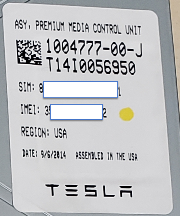
Tesla Premium MCU 1 Part No

IMPORTANT: If at all possible, try to get the cabling/connects that plug into the back of the MCU. This will make life INFINITELY easier for you. At a minimum, you would want the connectors shown below for the “Premium” MCU 1 device:

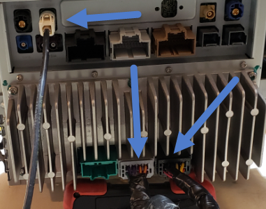
Figure 2 – Minimum Required Connectors

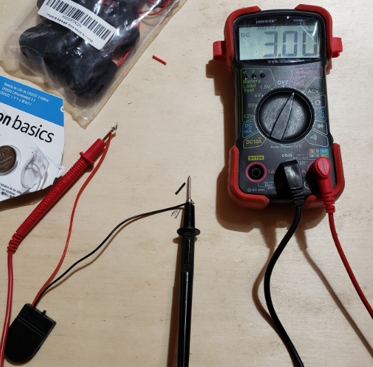
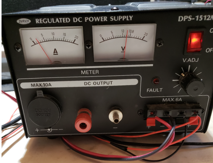
  • Power – The MCU will require a steady 12V source that is capable of providing ~3 Amps.
  • Soldering Iron – While not absolutely necessary, having a good soldering station will allow for a cleaner setup. I use the Hakko 936 which is a reliable entry level choice.
  • Ethernet cable – A small Ethernet cable, that you won’t mind cutting up.
  • Speaker – A small automotive speaker for connecting to the MCU to enable audio playback. This isn’t absolutely necessary, but it is a nice to have.
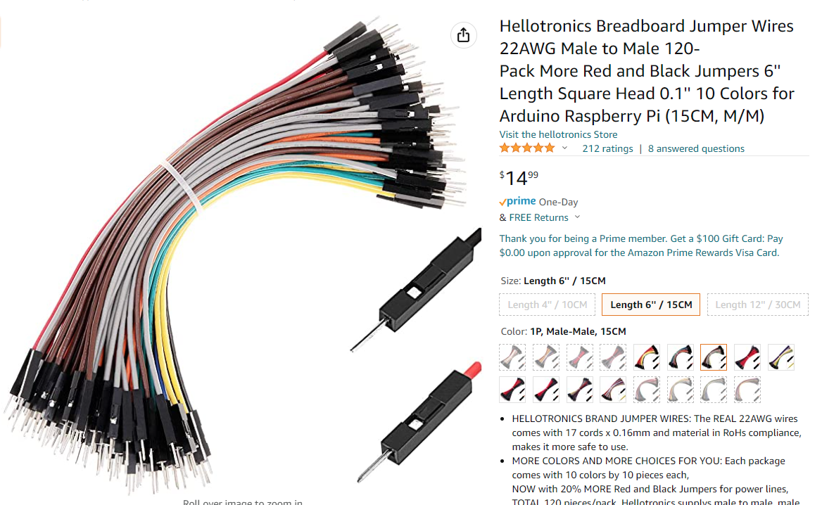
  • Misc. Electronic Project cables / Jumper Cables – These will be used to create the Ethernet to Tesla MCU “Fakra” cable.

Step 2 – MCU Wiring

In order to get the MCU running on our bench, there are 3 three main items that we need to wire up:

  1. MCU Power & Ground : Required to provide power to the unit so that we can interact with it.
  2. MCU Speaker : Optionally recommended so that you can hear audio chimes and/or listen to music while you work. ☺
  3. Ethernet aka Fakra connection : Require so that we can startup the unit, access OS via telnet, or execute REST API commands.
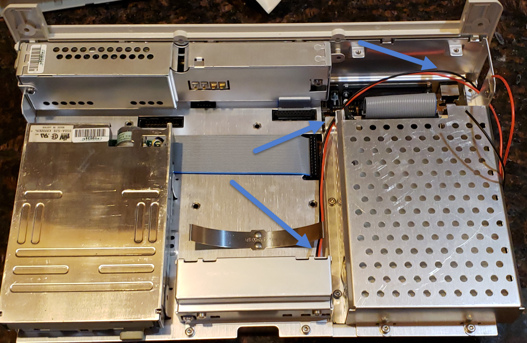
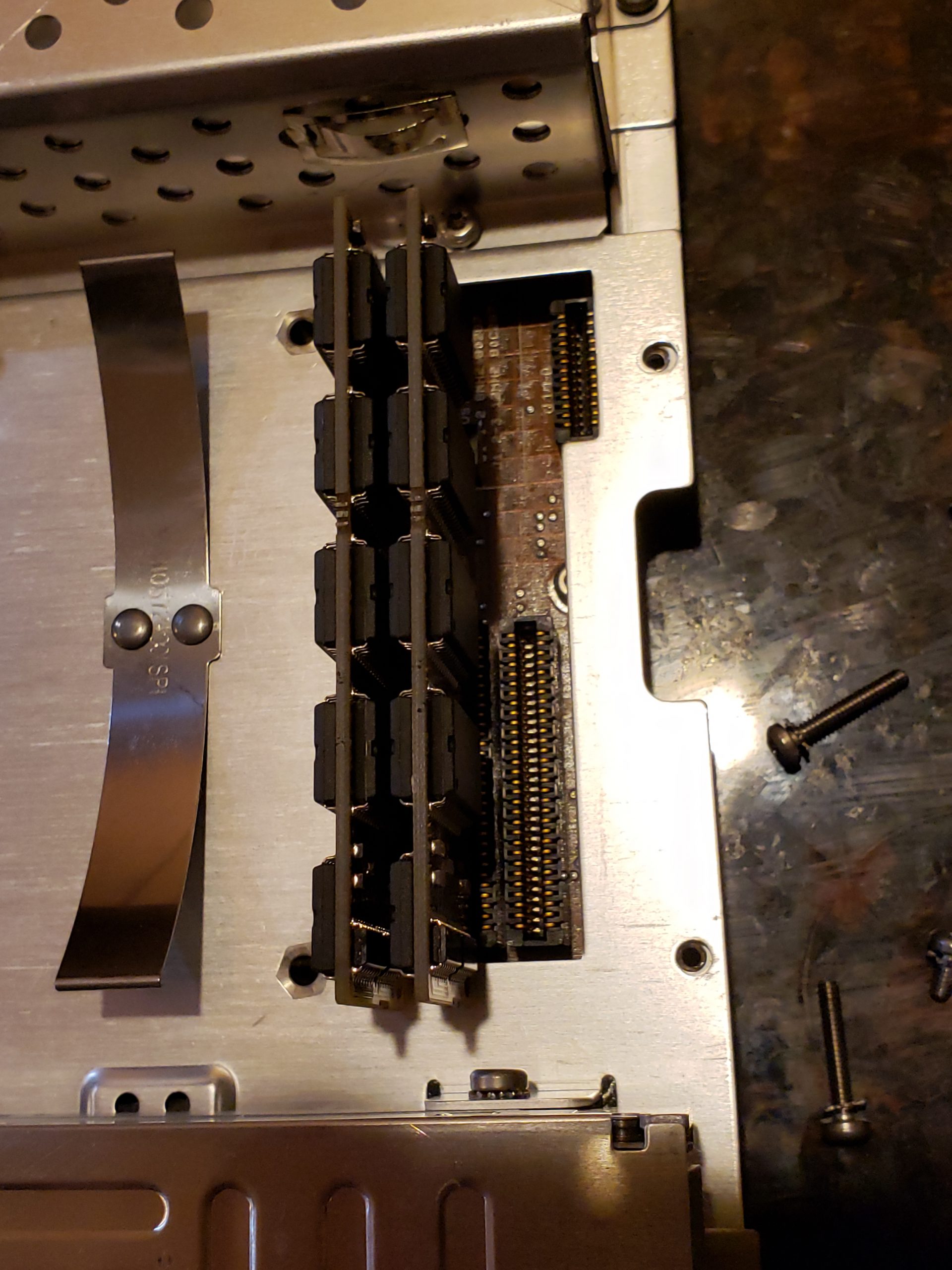
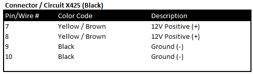
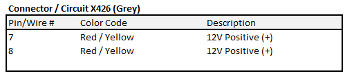
MCU Power & Ground

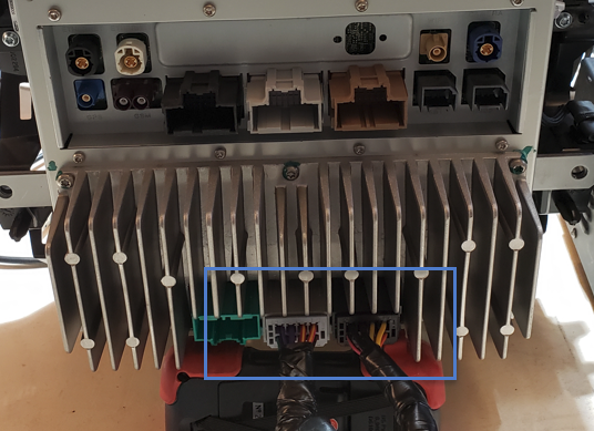
Wiring up the MCU for power is actually very straight forward and only requires a few positive (12V) and negative connections spread across two of the connectors. The two connectors are located on the lower portion of the MCU and are commonly referred to as X425 (Black) and X426. (Grey)

NOTE: In order to keep your wiring to the Power Supply clean, I recommend using a distribution block for + and – connections.

Close-up of necessary MCU power wiring connections.
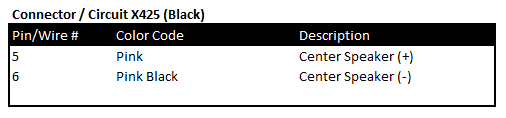
MCU Speaker

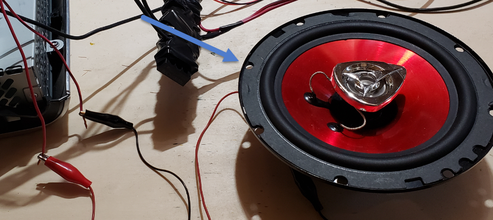
While you can wire up as many speakers as you would like, we only need the center speaker so that we can hear alert tones, etc. This speaker is also located on the X425 (Black) connector.

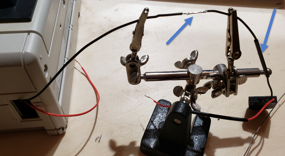
The easiest way to connect the speaker to these cables is to simply strip off the ends and use alligator clips:

Ethernet aka Fakra HSD connection

While the Tesla MCU utilizes Ethernet for certain actions, it does not provide you a convenient RJ45 port. The Ethernet connections utilize a “Fakra HSD” connector.

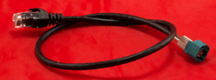
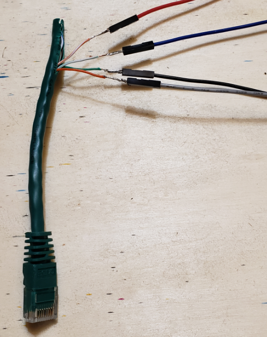
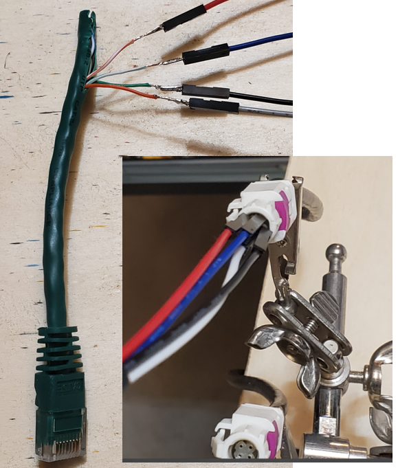
While you can buy these cables pre-made for ~$50, you can make one relatively easily once you know how to map out the HSD pins to the Ethernet cable wire.

The HSD cable consists of 4 pins consisting of two diagonal wire pairs where D+ / D- & Vcc / GND are pairs.

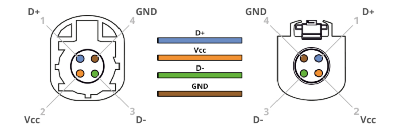
While a standard Ethernet cable consists of 8 wires / 4 twisted pairs, only 2 pairs are typically needed and these two pairs will be matched up to the HSD pinout as follows:

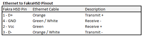
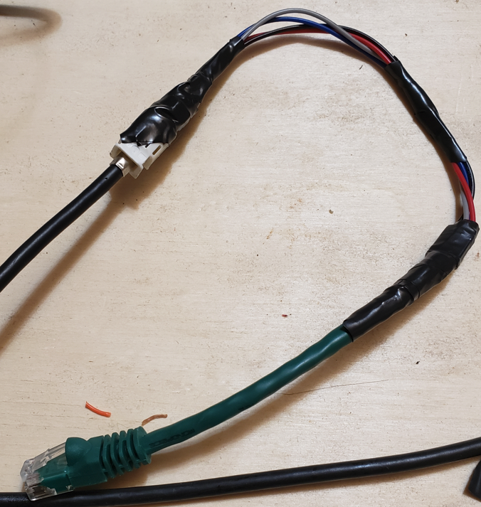
If making your own cable, the jumper wires I recommended at the start of this blog fit perfectly into the Fakra connector. I simply soldered one end to the Ethernet cable, inserted the other into the Fakra connector, and then taped it to ensure it doesn’t come loose.

C:\Users\317FX6~1\AppData\Local\Temp\SNAGHTML20204360.PNG

Step 3 – MCU Startup

Once you have completed all of the wiring in the previous step, you are ready to start the MCU! Next, perform the following actions:

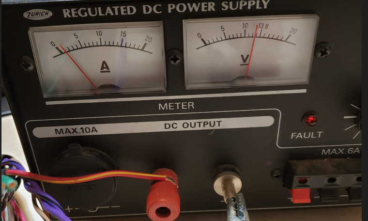
  1. Ensure that you have connected your positive and negative wires to your power supply and that the power supply is set to a 12V output voltage.
  2. Ensure that your speaker is connected.
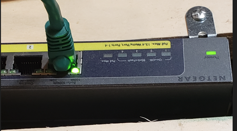
  3. IMPORTANT: Plug the Fakra/Ethernet cable into the back of the MCU and into either a network device (Hub/Switch) or to a laptop. Even if the MCU has power, it may not fully start unless it sees network traffic. [There are other ways to force it to start, but this is the easiest]

  4. Turn on your power supply – You will notice that at first, it is drawing a relatively low amount of amps, but once it fully starts, you will see the draw increase.
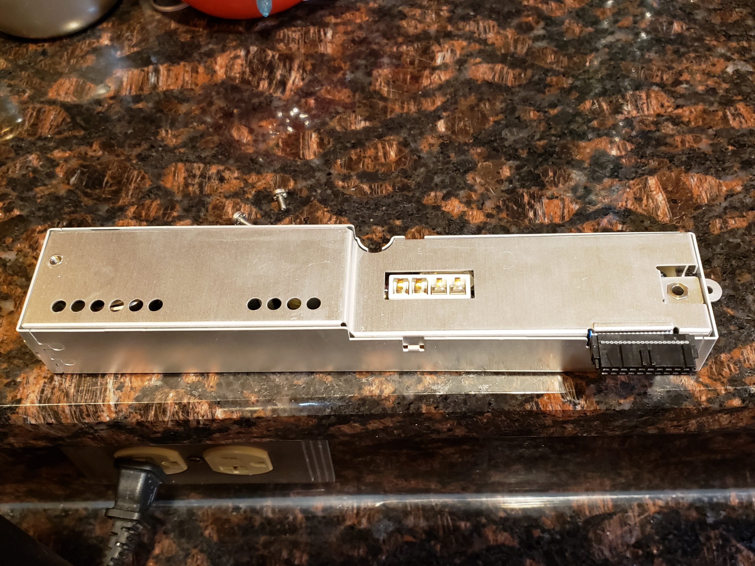
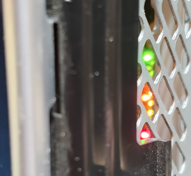
  5. Verify that MCU has power – If you look at the right side of the unit, you should see multiple LED status lights. Initially some will be Yellow/Red. Some will turn green as unit boots, etc.
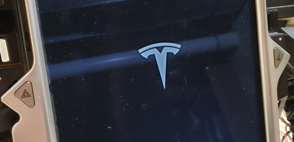
  6. Wait…. Wait…. Wait… It should take ~20 – 30 seconds to full boot up. If you have the speaker connected, you SHOULD hear a series of chimes around the same time the Tesla ‘T’ appears.
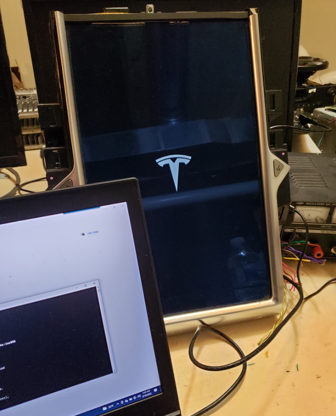
  7. Wait… Wait… Wait some more and then you should finally see the MCU come to life
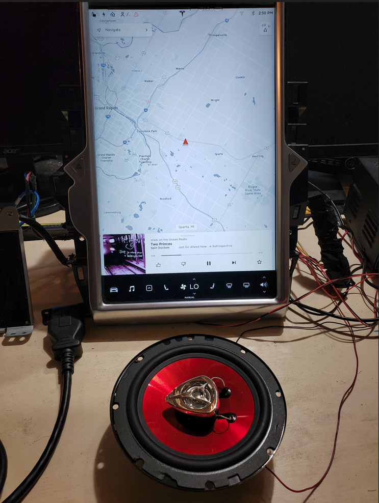
    Congrats! You now have a functional MCU on your test bench!

Retro Computer (Compaq SLT/286) “Steak Knife” Repair

Overview

Recently, I ran across someone looking to sell an “ancient” laptop that had been long forgotten in their closet for ~30 years. The laptop in question is a Compaq SLT/286. As I’m a sucker for very clean old tech, this was right up my alley! Since it was a Compaq machine, I was especially interested as I have a few of their previous ‘portable’ machines as well.

When I inquired about the machine, the owner state that it turns on perfectly fine; however, they were not able to do much else since it doesn’t ‘boot up’. The person stated that it was a work machine that was upgraded and prompt left, in its original bag, in their closet and was only recently discovered.

When I plugged in the machine, it did start up immediately; however, I was presented with a very familiar error message:

Issue

This error message is a clear indicator that the machine had “forgotten” certain configuration settings. In older computers, these Basic Input / Output Services (BIOS) settings are stored in a Complementary Metal-Oxide-Semiconductor. (aka CMOS) The CMOS requires a small amount of power to retain its memory. The earliest PCs typically had a small battery attached to the motherboard which would provide this power. Unfortunately, batteries do not last forever and will fail. In a best case scenario, the battery simply fails to produce enough power while in worst case scenarios, the battery loses integrity and acid can damage the motherboard.

Worst Case Example: Compaq Portable II w/ catastrophically failed battery

Fortunately, this Compaq model did not use a battery that could fail in such a manner and the motherboard was clean as a whistle. (see all the disassembly pics at the end to see just how clean this machine is!)

A quick scan of the motherboard also reveals that there isn’t a battery per se. For this computer, Compaq chose to use a Dallas Real Time Chip (RTC) module which stores the relevant information. This device, which is still used to this day in certain applications, performs multiple activities: “nonvolatile” RAM memory, supports certain Read Only Memory (ROM) operations, and Real-Time Clock (RTC) operations. The one “gotcha” to this device is that the RAM is non-volatile only because there is a battery hidden inside the module which provides power to the device. Once this internal battery is depleted, it is no longer a nonvolatile RAM device.

The image on the left is the module found on this Compaq’s motherboard. The ‘8849’ is the build date for the module which corresponds to the 49th week of 1988! The image on the right is an X-Ray of this type of module. The power source is the circular item near the middle of the module. (X-Ray image courtesy of https://ardent-tool.com/)

CMOS Repair

In order to get this PC up and running, we will need to address this failed module. There are a few options:

  • Replace the Dallas RTC module with a newer one
  • Carefully modify the existing Dallas module to power it from an external source

As with any repair, there are always trade-offs to consider. In this scenario, I chose to supply external power to the existing module for the following reasons:

  • The existing module is directly soldered to the motherboard. This would require me to desolder the existing module and then solder a new one to the board. While this is not overly difficult, it requires a bit more effort and care than the other option. (If Compaq had placed the module in a socket, I would have opted to replace the module)
  • Many suppliers of compatible Dallas RTC modules are selling “New Old Stock” (NOS) components. Because of this, the batteries may only last for a few years before requiring replacement again.
  • Accessing the module requires a complete disassembly of the unit. (disassembly pictures are in a later section)
    • If I’m going to have to replace a battery again, I’m strongly prefer to *NOT* have to disassemble the unit
    • NOTE: As you’ll see later, my repair allows for a 60 second battery replacement and requires no tools.
  • This approach is relatively low risk. If I make a mistake accessing the internal battery, I can always resort to replacing the module. If someone else acquires this machine and would rather replace the module, they can still do this.

The following steps were performed to implement the external battery solution:

  1. Carefully remove the top layers of the Dallas module’s epoxy to expose the battery
  2. Disconnect the battery from the module pins
  3. Solder new leads to the power pins
  4. Route wires to a convenient location
  5. Solder coin battery holder to other end of leads, add battery, and verify power

Module Modification

If you’ve read this far, you are probably wondering: “Why did Charles mention he used a steak knife to effect this repair”? If so, you don’t have to look any further! To cut into the module, I choose to use a nice and sharp steak knife! While a Dremel would have been more surgical, it was in the garage and I didn’t feel like trekking into the cold to fetch it. As the epoxy/resin material is relatively soft, I had no trouble using a knife to accomplish this task. Once the battery was exposed, a small wire cutter was used to disconnect the existing battery. Next I prepped some wires, soldered them to the appropriate pin outs, and sealed it with my glue gun. (Yes, I could definitely have made this cleaned, but I wanted to make sure it was working first…)

Wire Routing & External Battery

I gave myself plenty of extra wire so that I could route it to a spot where it wouldn’t impact the operation of the laptop *and* it could be easily accessible.

(Look how clean this unit is! Amazing)

I then put together the coin battery holder and verified that I was getting proper voltage.

Next, I soldered the coin battery holder to the module wires. (Always use heatshrink!)

Finally, I wrapped the holder in electrical tape and tucked this into the access port on the side of the laptop. This convenient location will allow a battery swap in seconds without the need for any tools. If I add the optional model, I will need to relocate this; however, it is a perfect location for now.

With the machine physically repaired, the only thing left to do is create the Compaq Diagnostic Disk and reconfigure the device.

Software Reconfiguration

After scouring the internet, I was able to locate the appropriate software and used it in yet another retro machine to create the necessary software:

I insert this newly created disk into the Compaq, turned it on, and the configuration utility started. The utility seemingly auto-detected everything auto-magically.

After saving the configuration, the machine started up w/o any error messages!

It Lives!

After exiting the configuration utility, the computer sprang to life and I was greeted with a DOS prompt. Looking around on this machine, I found some pretty standard late 1980’s business programs. Quite a trip down memory lane.

1-2-3

WordPerfect

PFS Write

Bonus Pics

Below are disassembly and other pictures that didn’t make the cut up above. Take a look at how clean this machine is. Amazing for the age. Also, if you made it this far, there is a hint for my next post. Something else running on that workbench is a bit out of place….. If you recognize it, feel free to point it out and take a guess what we’ll be doing with it!

Compaq Portable Family

The largest machine is only a couple years old. Amazing at how much they shrunk down the electronics! Another post is going to dig into that machine and you will be able to see the difference!

Disassembly


Electronics Project Room …..


I’ve been slowly repurposing a spare room in the basement to serve as my electronics project room.  Not quite done, but thought I’d post some photos showing current status.  Just need to get the electrical finalized and will be good to go!


Primary Work Area
Bench #1


Decorative / Functional Gauges

Oscilloscope & Stuff

Trusty Hakko 936
Hakko 936 Soldering Station & EMP 20 Programmer

5 1/4″ Floppy Fun

Recently I was asked if I could recover some data from some old 5 1/4″ floppy disks. As I kept my old 8086 computer laying around “just in case”, I was more than happy to oblige!  I took the disks and began my challenge laden journey to get the data into a modern system.

Bringing ‘ole faithful back to life

After a quick search of my electronic scrapheap, I located my first IBM-PC compatible computer that I ever owned, an Epson 8086!  Like the Millenium Falcon from Star Wars, it may not look like much, but it has it where it counts!  (e.g., it has a working 5 1/4″ disk drive!)  For those who are interested, here are the specs to this late 80’s powerhouse:

'Ole Faithful
My first PC, an Epson 8086 4.77 Mhz w/ 10 Mhz “Turbo” mode!

Epson Apex 
CPU    : Intel 8086 Processor, no Math Co-processor
Speed  : 4.77 Mhz w/ 10 Mhz 'Turbo' Mode
Memory : 640 KB Conventional RAM, no Extended or Expanded RAM
Video  : CGA Graphics - 256 colors in text mode, 4 colors @ 320x200 graphics resolution 
HDD    : 20 MB RLL Encoded Hard Drive 
Floppy : 360 KB 5 1/4" Drive
Ports  : 9-Pin DIN Keyboard, 25-Pin Serial, 25-Pin Parallel

Just like the Millenium Falcon; however, I had performed a slight modification to this computer, a Microsoft Mach 20 add-on board!

Microsoft Mach 20 Board
CPU    : Intel 80286 Processor
Speed  : 8 Mhz 'Turbo' ("Equivalent to 12 Mhz 80286's of the day")
Memory : 512 KB RAM, expandable to 3.5 MB

The board works by replacing your 8086 Processor with an special adapter that connects the Mach 20 board to the computer’s motherboard.  The additional RAM is recognizable as Extended (first 384 KB) and Expanded  (remainder) by including HIMEM.SYS and EMM386.SYS in the MS DOS config.sys file.

Why am I mentioning this board you ask?  It was the first obstacle between me and my data!

Well I guess the 20, in Mach 20, refers to its lifespan….

I hooked up the keyboard, the monitor, and power cables and hit the Hyperdrive. (Power button)  The lights in my workout room momentarily dimmed and the screen flickered with a BIOS self test, perfect!  The memory test systematically ran through the memory: 64 KB, 128 KB, 256 KB.  Just as I thought things were going well, failure!  The screen froze at 256KB and then the screen went dead.  I shrugged it off as a fluke and punched the button again.  Once again, the memory test began: 64 KB, 128 KB, 256 KB, 320 KB, 384 KB.  Once again, I was met with a resounding failure as it froze again.  I looked over the internals of the computer and at initial glance everything appeared to be in order.  As I started feeling the connections, I discovered that the Mach 20 CPU connection cable felt suspect.  On a hunch, I held the cable down and hit the switch again.  64 KB, 128 KB, 256 KB, 320 KB, 384 KB, 448 KB, 512 KB, 576 KB, 640 KB!  Success!  I quickly shut off the machine and placed one of the our epoxy coated 5 LB dumbbells on the connection.  With the Mach 20 situation addressed, I was on the fast path to getting that data….. or not …….

Anyone have a 9-PIN DIN Keyboard laying around?  I didn’t think so ……

As I restarted the computer and watched the memory test complete, I was greeted with the next obstacle: BIOS test failures!  The first error was a lovely 301 Keyboard error.  As the picture at the beginning of this post should attest, the keyboard has seen better days and it was very, very unhappy.  As I don’t keep spare DIN keyboards laying around and it was ~ midnight, I didn’t have any options other than to find a way to make it work.  After disassembling the keyboard, I found significant corrosion on the connectors.  I cleaned the corrosion and reassembled what was left of the keyboard.  Fortunately, this was sufficient to allow the BIOS keyboard test to pass!  Later into the process of recovering the data, I discovered that some buttons didn’t work on the keyboard which made typing  difficult, but not impossible.  (HINT: ALT + ASCII code will put a character on the screen)

Floppy Drive Cable, Where Art Thou?

After resolving the keyboard failure, I was presented with yet another BIOS test gift, 601 – Diskette Error.  As the whole point of thisAfter awakening from a 20 year slumber, my computer was not happy. exercise is to read data from the floppy disk, this error was especially cringe worthy.  After staring at the screen momentarily in a mixture of disbelief and annoyance, I took another look at the cabling and discovered a likely explanation for the problem:  there wasn’t a floppy drive cable!  Even though it had been over a decade since I last used this machine,  I tried to come up with a reason why the cable would be gone and came up completely blank.  (still don’t know)  I searched through my bin of spare cables; however, this was a cable I didn’t have since these cables are nothing like current drive cables.  Defeated, I retreated to my laptop in search of a cable. In an amazing stroke of luck, Fry’s electronics stocks these cables and I picked two up in the AM.  (I have no idea why they stock this cable, but I’m sure glad they had it!)  I connected the cable, fired up the machine, and all BIOS tests passed.  The machine booted up DOS and things were finally falling into place.  I inserted the 5 1/4″ floppy, type A: to access the drive and ……..

Abort, Retry, Fail?

Anyone who has worked in DOS knows this message and the fear it creates as you realize your data is probably corrupt and gone forever.  While I set early expectations that the 5 1/4″ disk may not be recoverable due to its age, the disk was well stored and  I was really hoping to get this data.  I wasn’t ready to let it die on the operation room table! (actually my workout room floor, but who is keeping track…)  I futilely tried to access the drive repeatedly.  Each time I was met with the same cold message.  I looked at the clock and almost called the time of death on my data recovery effort, but I wanted to try one more thing.  Looking very closely at the disk, I noticed that it didn’t appear to seat entirely into the disk drive.  Even though the locking mechanism closed, the disk drive started up, and it sounded like it was working, it didn’t look quite right.  I used my left hand to push the disk into the drive farther and then tried to access the disk again.   Success!  Treating the disk as if it were an self destructing Mission Impossible message, I quickly copied the entire contents of the floppy disk to the computer’s hard drive.  I basked in the successful data copy for a few moments and then realized that my job wasn’t close to done.

Congratulations, you’ve moved your data from an obsolete 5 1/4″ disk to an obsolete computer, now what?!?!?

While I was able to read the data of the floppy successfully, I still had to find a way to get it to the person needing the data.  This antique didn’t have an Ethernet card (or software to run it) so I couldn’t email, FTP, or directly move the data across a network.  The machine didn’t have a 3 1/2″ disk drive which could be more useful.  I didn’t even have a modem.  There were two options that came to mind:

  • Transplant the hard drive into a more modern computer – While at first this may seem like a dead end, this is actually a very viable option.  Even though the hard drive is an older format which a newer computer wouldn’t recognize, I could move the controller card AND the hard disk into a newer machine with ISA slots and it would work!  (I’ve done it once before)  I grabbed the oldest/modern machine I had laying around, an HP Pentium based desktop, ripped it open and ……..    *NO* ISA slots.  Unfortunately, it was just new enough that it had PCI; therefore, I would not be able to move the hard drive and needed a Plan B.
  • Transmit the data over the Serial / Parallel ports to another computer – Thinking back to my old DOS days, I recalled a program built into the later versions of DOS that would allow you to send files between computers.  After combing through the DOS folder, I located the program:  Microsoft Interlink.

My victory was once again short lived as a few realizations set in:

  • Microsoft Interlink needs to run on both the host AND destination computers – As newer computers don’t ship with this program, I would need to get it copied over to the destination machine.  Of course if I had a way to copy that file, I wouldn’t need the program in the first place………   After a lot of scouring, I found a someone who was hosting the necessary files!
    http://www.pcxt-micro.com/dos-interlink.html
  • Microsoft Interlink needs a “LapLink” or Null modem cable – No problem, I know I have a Laplink cable here somewhere………..  I searched through my spare cable bin and my cable was nowhere to be found.  Unfortunately I gave away a large amount of older computer items just weeks before I took on this task and I suspect it was one of the items I gave away.  (After all, who would need an old LapLink cable, right?)  That’s OK, lets make our own….

Microsoft Interlnk, the gift that keeps on giving!

Using EDLIN to update the CONFIG.SYS to load INTERLNK driver

A quick scan of the Microsoft website (http://support.microsoft.com/kb/121246/en-us/), as well as the Interlnk help file, provided all the information necessary to wire up the pins.  In a huge stroke of luck, the prototyping cables I use for my circuit work perfectly fit the serial port pins making connecting the machines quick work.  The only drawback is since the cables are relatively short, it was a bit of a challenge to hook everything up.  With the cables connected to the computers, I turned my attention to configuring the software.

As I alluded to earlier, both machines need to have software running for this to work, the following steps outline what needs to happen:

  • Place INTERLNK.EXE and INTERSVR.EXE on both machines
  • Update the CONFIG.SYS file to load a device drive as follows:
    DEVICE=C:\DOS\INTERLNK.EXE /<ltp|com>:<number>  where:
  • <ltp/com> – specify LPT if connecting through a parallel port, com if connecting through serial port.
  • <number> – is the port number (i.e. If connection to LPT2 / COM2, enter a 2 here)
  • Update the AUTOEXEC.bat to call the INTERSVR.EXE program
    C:\DOS\INTERSVR.EXE
  • Ensure the cable is connected between the machines
  • Restart the machines

Directly Connecting Computers using Prototype Circuit Board jumper cables

If everything is setup right, during the boot-up process you will see a message indicating that a link has been established and it will assign a local drive letter to the remote system.

Success at last!

After restarting both machines, Microsoft Interlnk loaded and a drive map was established between the two machines.  I copied the files over to the newer machine and then used a IDE-USB adapter to connect that computer’s hard drive to my laptop and send the files off.

Connection Established!

It wasn’t pretty, but in the end everything worked out and I got to justify keeping my old 8086 around!

Since it is up and running….

After I had successful sent off the files, I went back to the old 8086 to see what was still on the machine.  I found a couple of old, but good games that I used to play and some old code I wrote to add mouse support to a BASIC program I was writing.  A nice trip down memory lane!

Centurion 688AttackSub ASM to Activate Mouse Cursor GottaLoveCGA