Browse Category

Reverse Engineering

Tesla Reverse Engineering: MCU Teardown

Overview

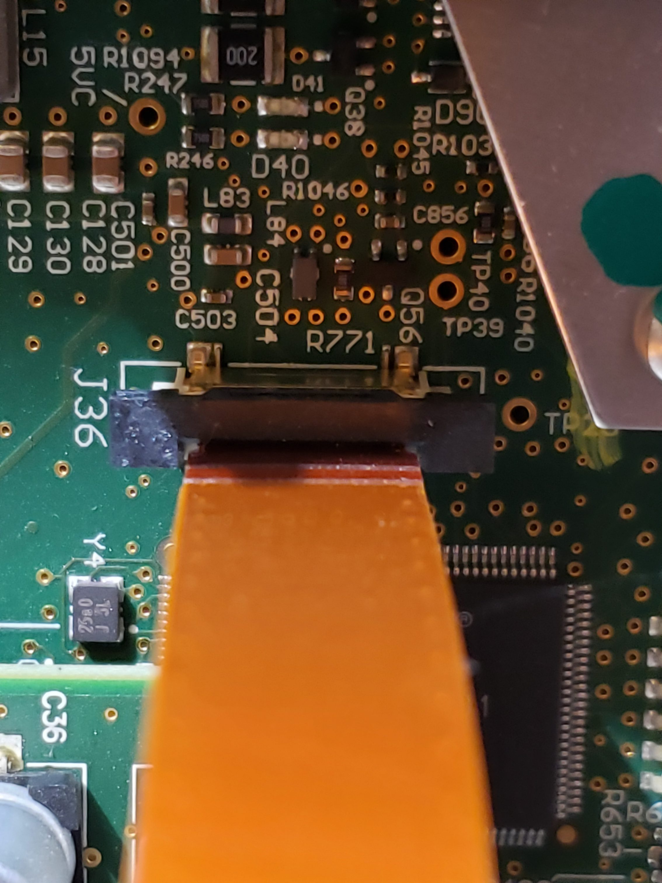
When reverse engineering an important, and rather fun, step is disassembly. Digging into the internals of hardware & software typically provides many clues as to how you can exploit a system. If you know what technologies are being utilized, this will make it easier to understand how the product works and how to exploit it. Additionally, by knowing what key components / technologies are in use will give you a starting point for finding attack vectors. (E.g. known vulnerabilities) Additionally, in many cases, an analysis of the hardware will result in the discovery of diagnostic/debug access to the system. This is especially true for the Tesla Media Control Unit (MCU)

The MCU, which has numerous implementations, is a complex device which is critical to the operation of the Tesla vehicle. The MCU serves as the primary user interface for vehicle control/configuration, navigation, radio, entertainment, communication & coordination w/ other vehicle modules, diagnostics, and remote communication w/ Tesla HQ. Given the complexity of this unit, any/all clues to its operation will be extremely helpful in understanding how it operates. A full tear down & inventory of key components is ONE method to increase our knowledge.

The MCU consists of the key sub-assemblies:

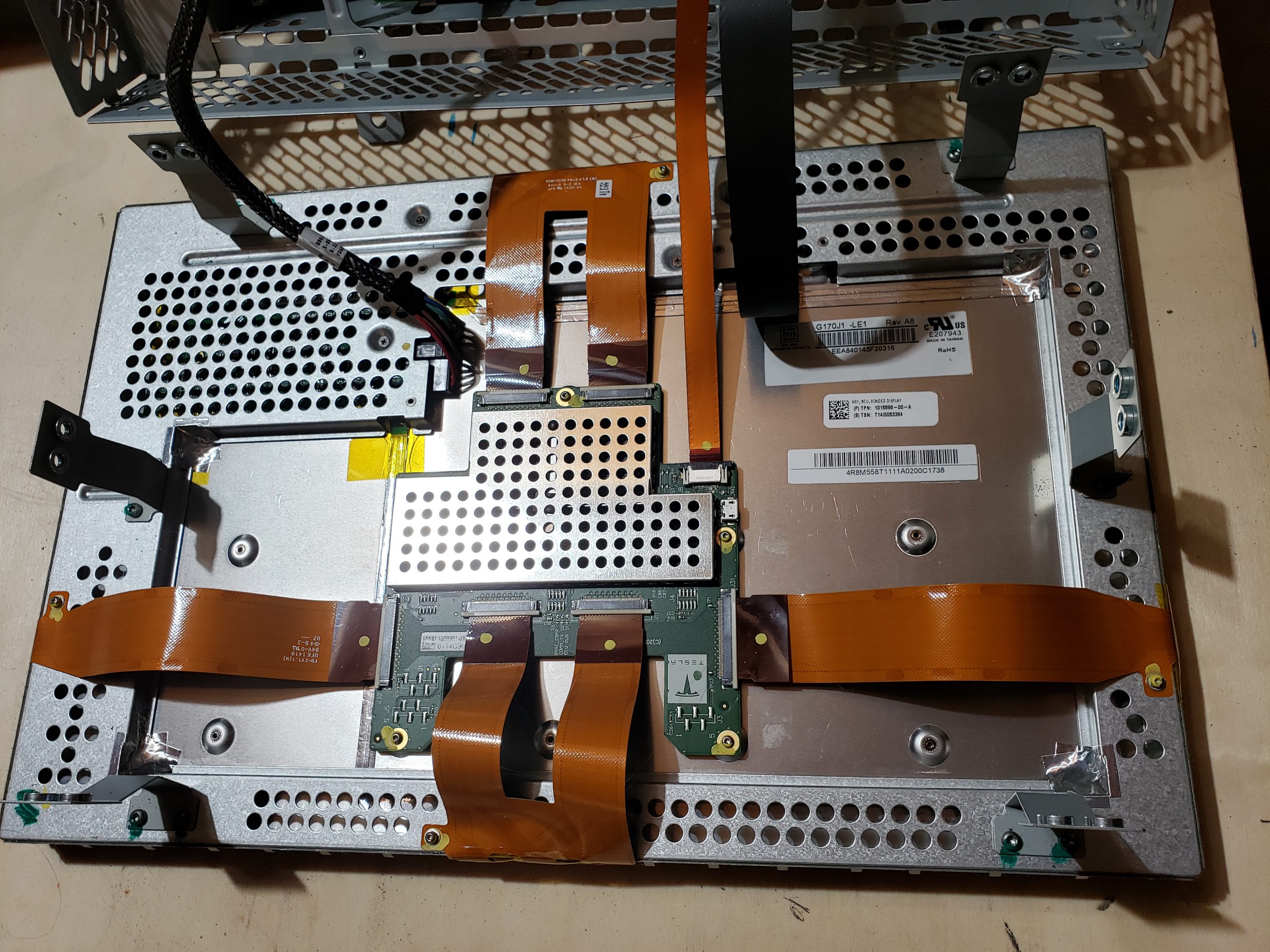
  • Bonded Display – For most people, this is the only assembly that matters as it collects user input and provides visual feedback.
  • Amplifier Assembly – Audio amplifier module which drives speakers, etc.
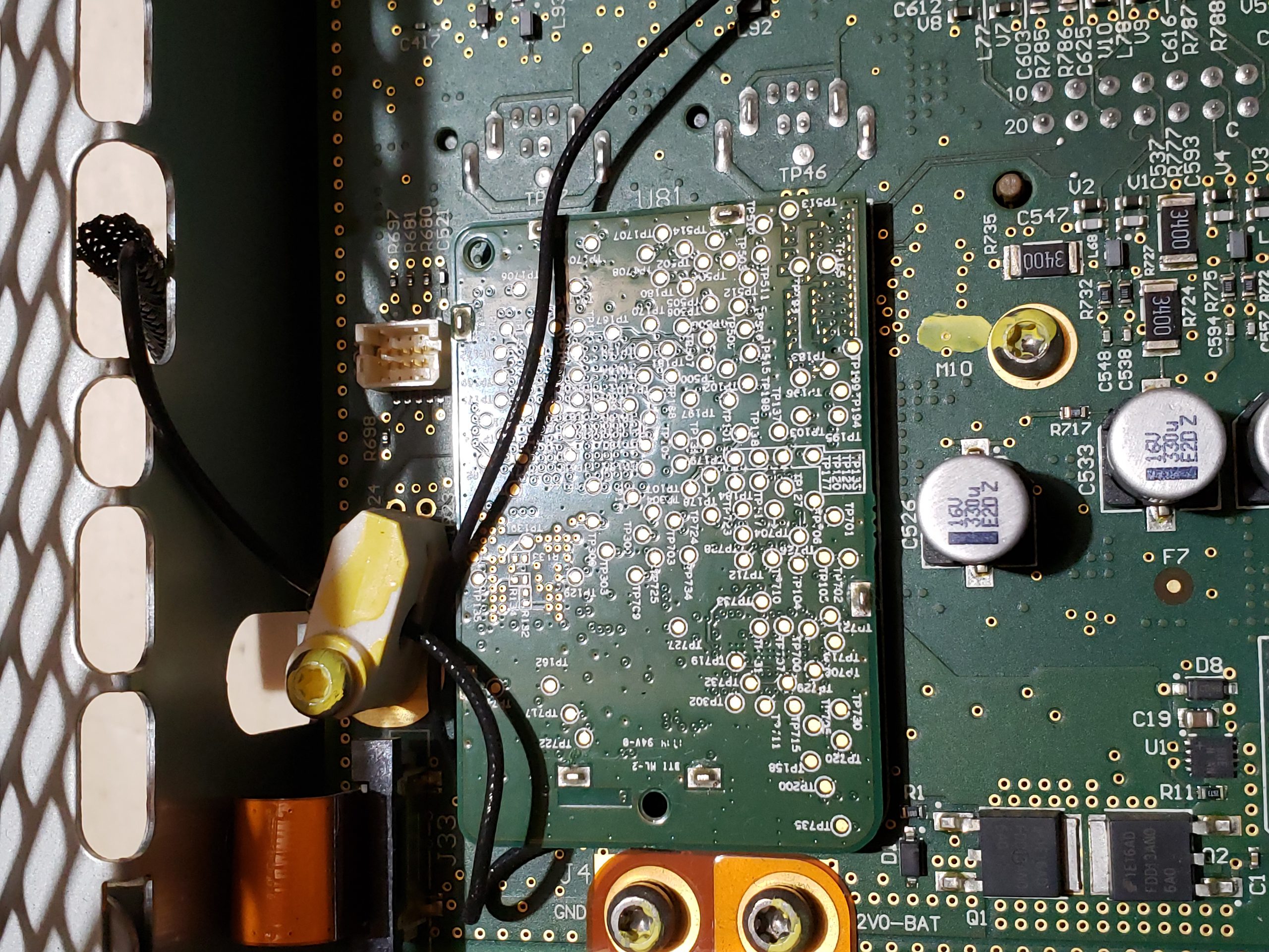
  • Cellular Communications – This sub-assembly is responsible for cellular communications. Early MCUs supported 3G while newer sub-assemblies support 4G/5G.
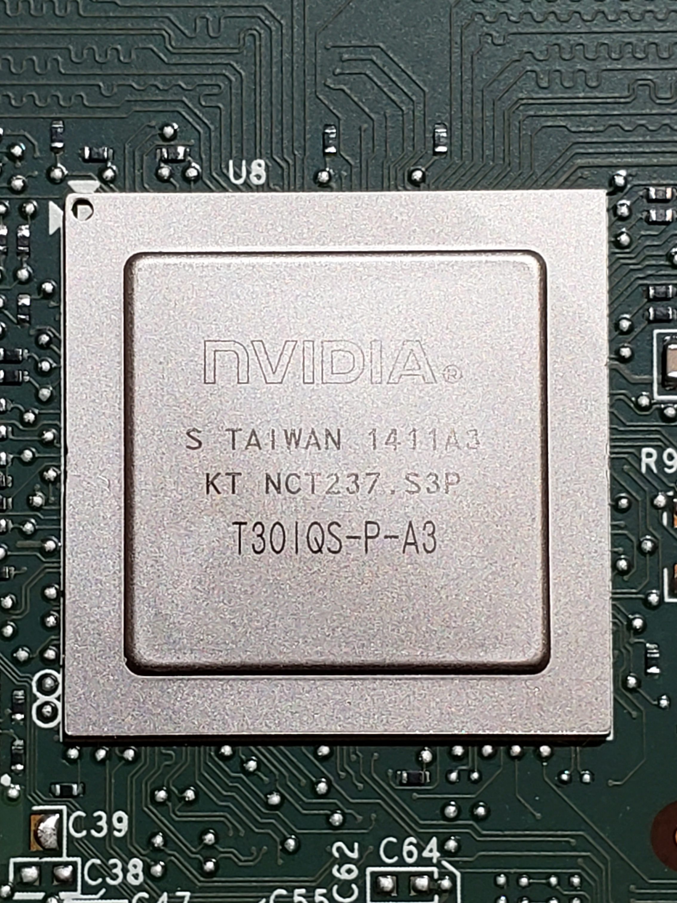
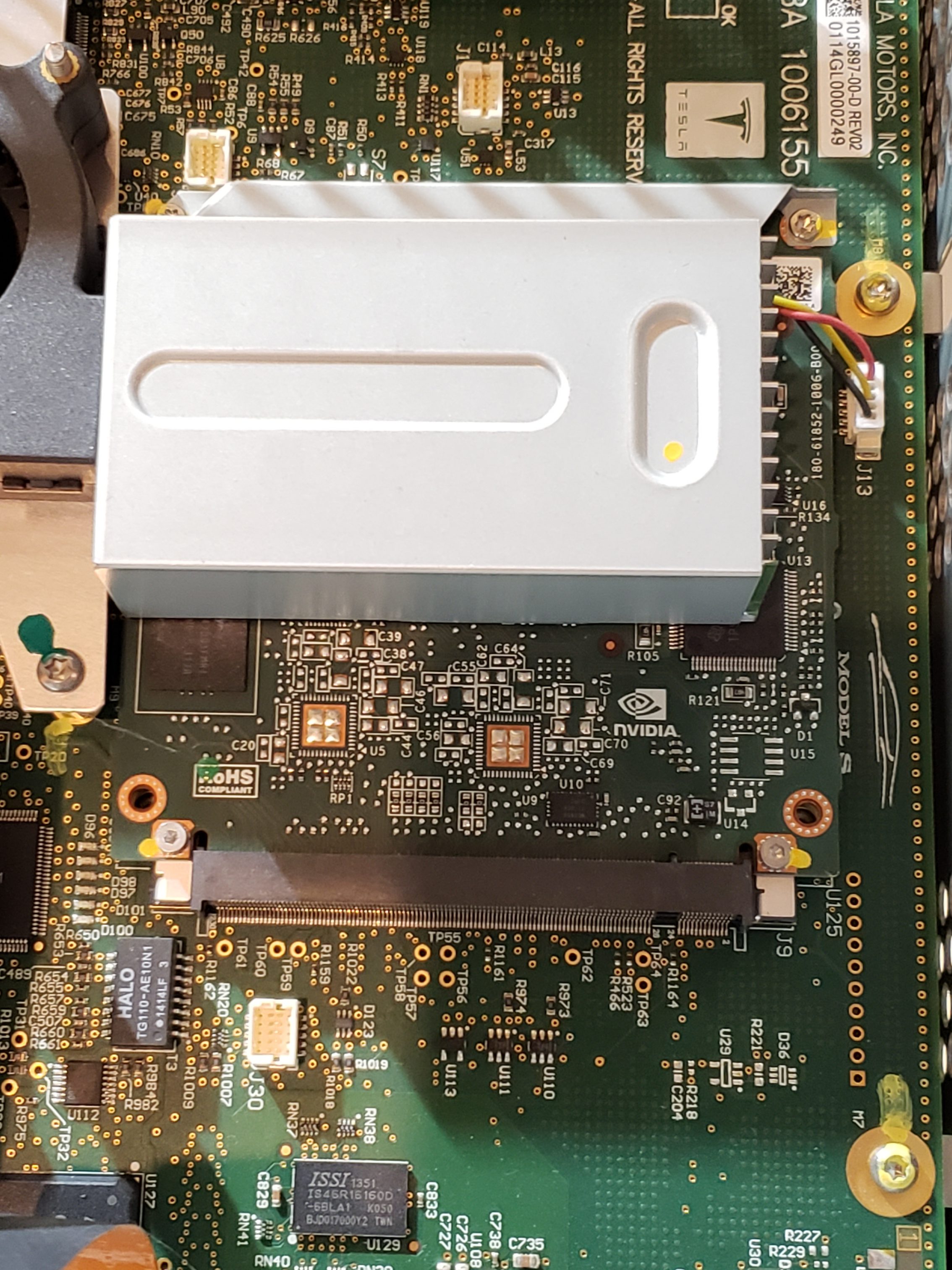
  • Infotainment Processor – This sub-assembly provides the main processing power for the MCU. For the MCU 1, this is powered by NVidia while MCU 2 utilizes Intel Atom, and MCU 3 contains an AMD Ryzen processor.
  • Main Board – This is the largest assembly and serves as the hub for all of the other sub-assemblies.

Bonded Display

From a reverse engineering perspective, this is probably the least interesting sub-assembly. The electronics are relatively minimal and single purposed. I don’t expect there to be much value in focusing on this assembly. With that said, there is a USB port on the control board. I suspect this is probably used for pushing firmware in the factory.

Amplifier Assembly

Similar to the display, this assembly is also very single purposed and I don’t see any obvious value in focusing too much time here. A quick review of the circuit board does not find anything remarkably useful for reverse engineering purposes.

Cellular Communications

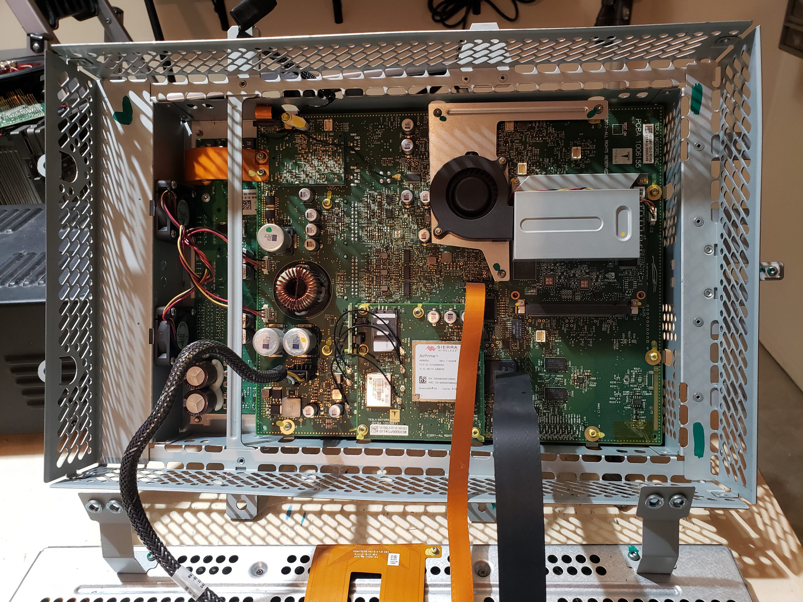
This module is far more interesting as it is responsible for remote communication, which is quite valuable. There are multiple prominently displayed components on this board of note. Additionally, you’ll see that this contains a removable SIM card. As the older modules came with “unlimited data”, perhaps you can repurpose this? ☺ It would additionally be curious to see if any data is on this card.

Infotainment Processor

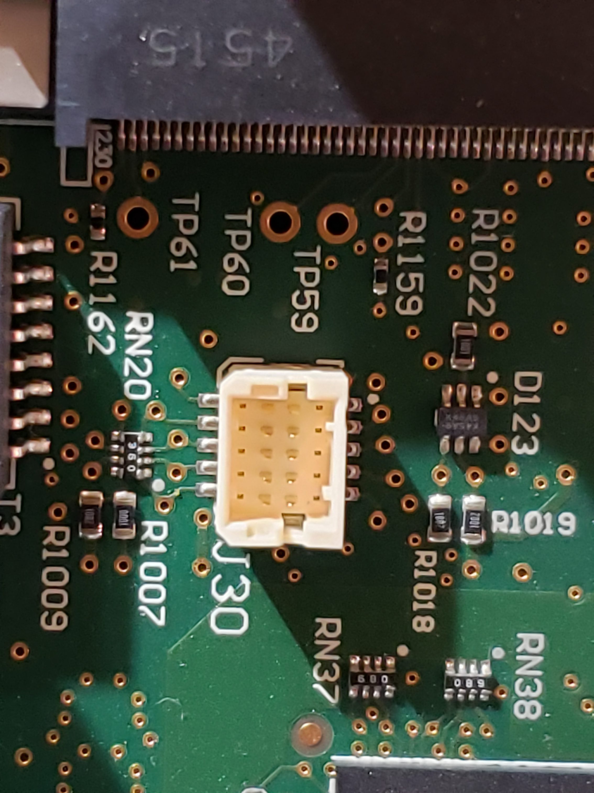
The infotainment process assembly is another “high value target” as this is the primary “brains” of the MCU. In addition to the NVIDIA processor, this board contains SDRAM, e-NAND Flash Drive*, a USB Hub, Ethernet controller, and an IC flash device. In additional to the components, on the board, there are a couple of unpopulated pads. Perhaps these pads are simply for optional components or perhaps they are for diagnostic purposes. More investigation is required to determine if they are of any value.

* – Due to how the Flash Drive has been utilized by Tesla, these devices are beginning to fail in older MCU 1 vehicles. When they fail, the MCU will operate erratically eventually resulting in the “black screen of death”. There is a recall and Tesla will replace these sub-assemblies with a newer/higher capacity flash memory. If you are skilled, you can repair this yourself. ☺

Main Board

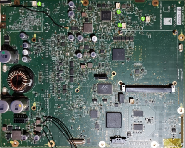
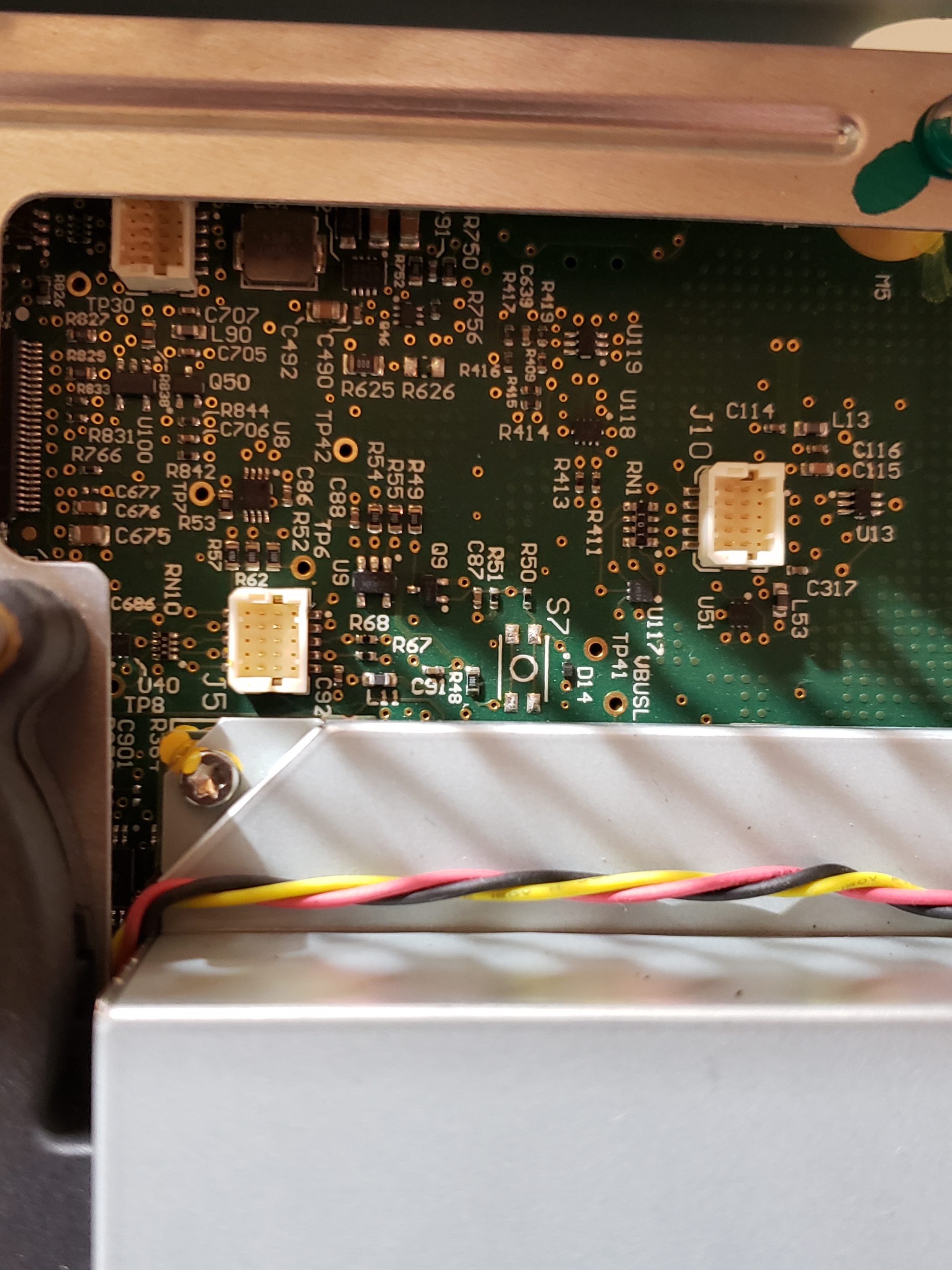
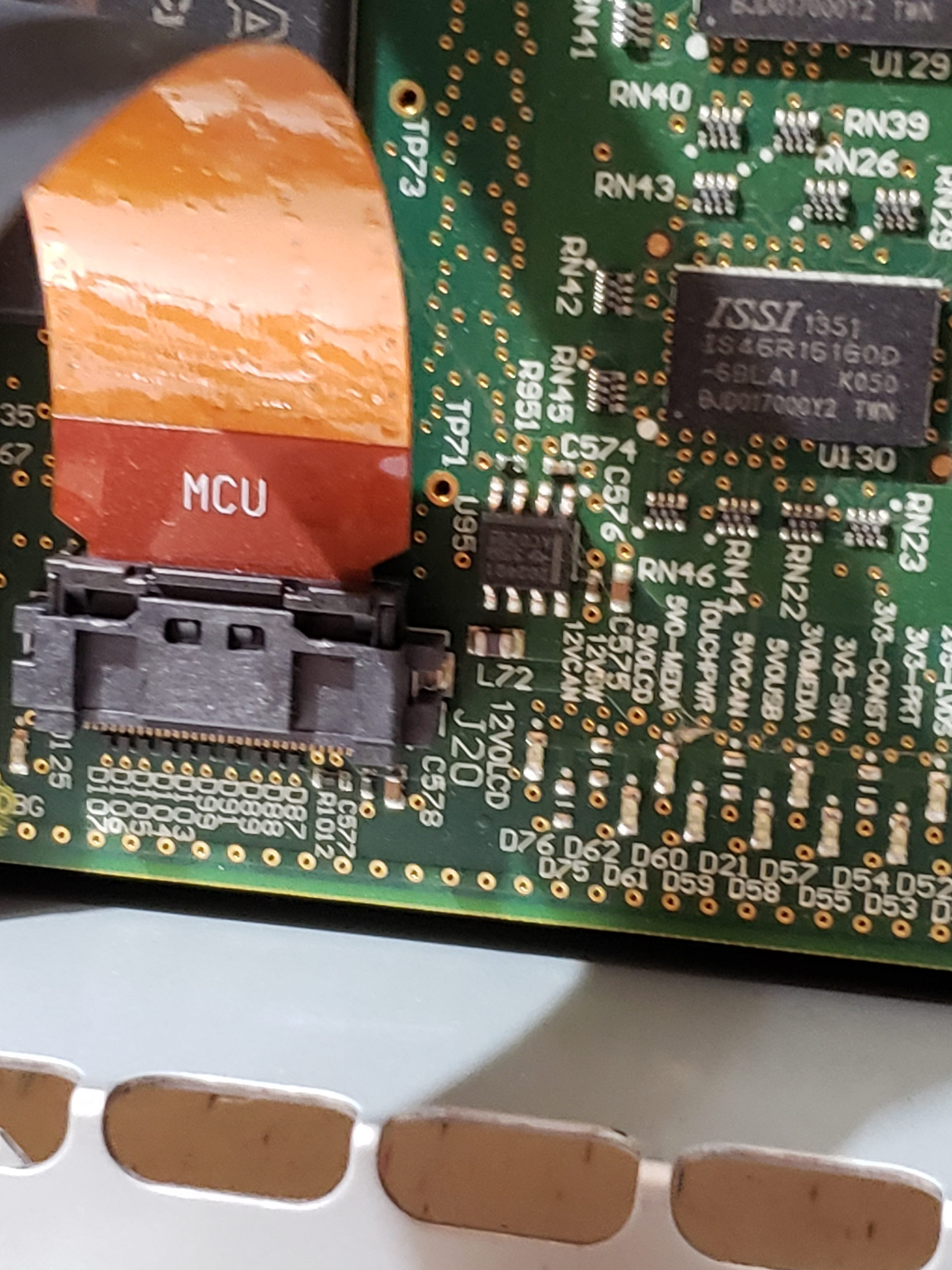
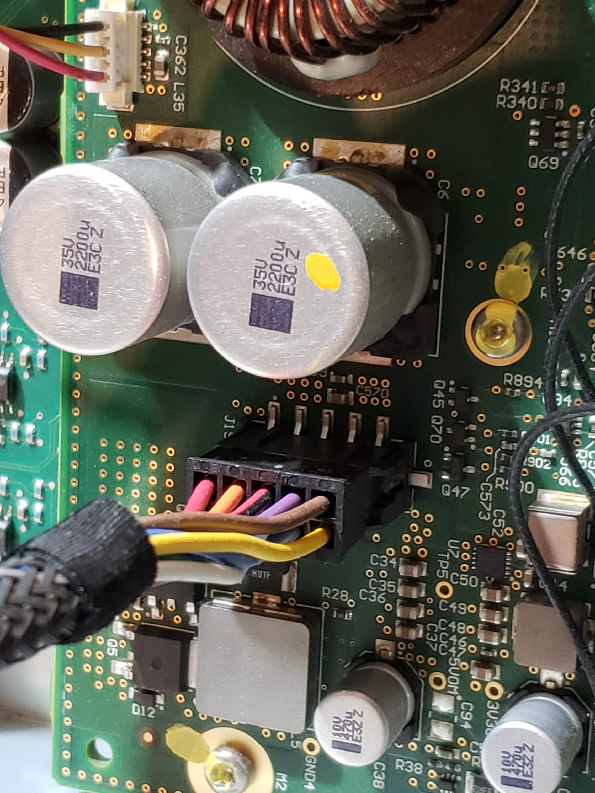
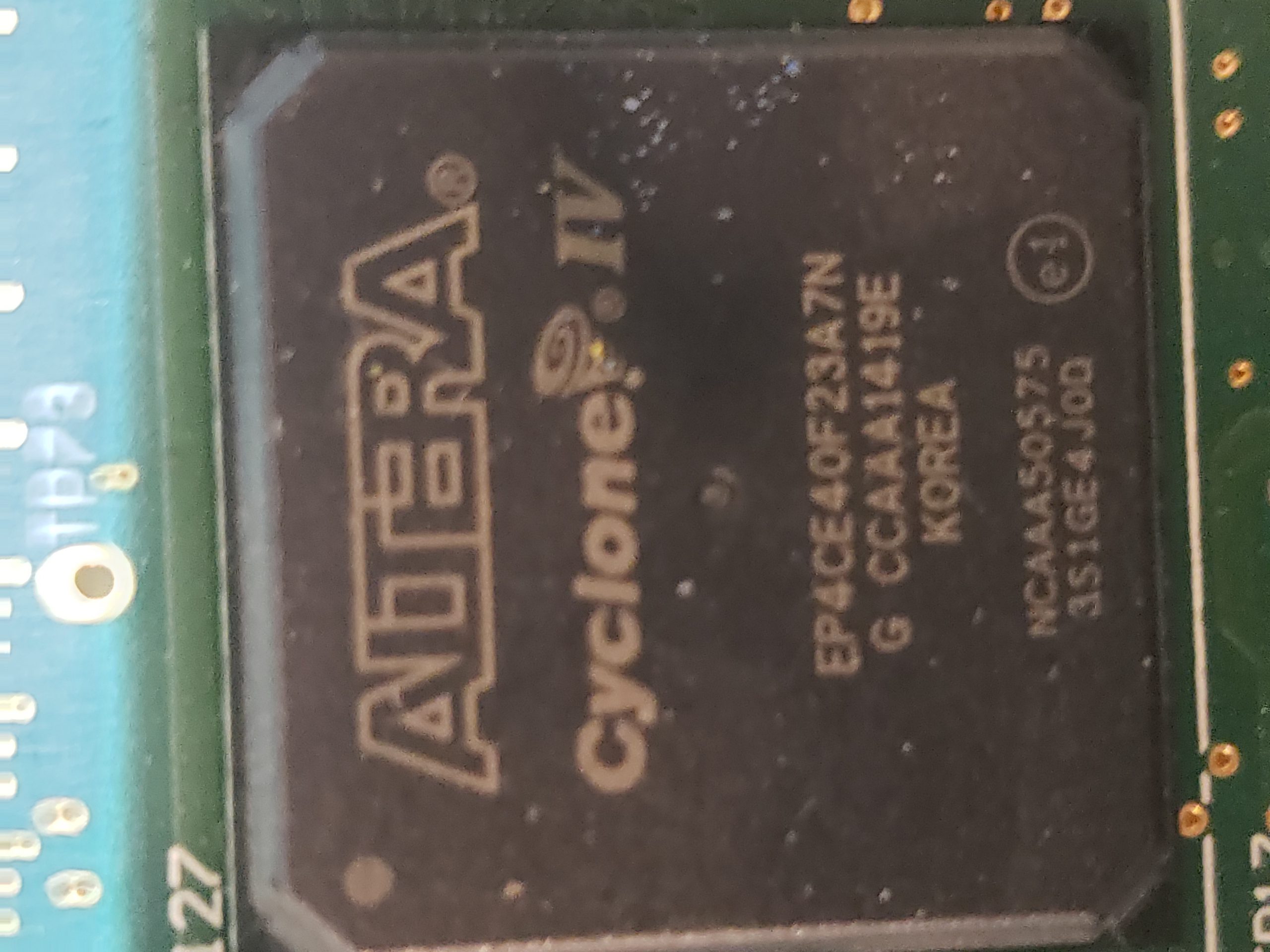
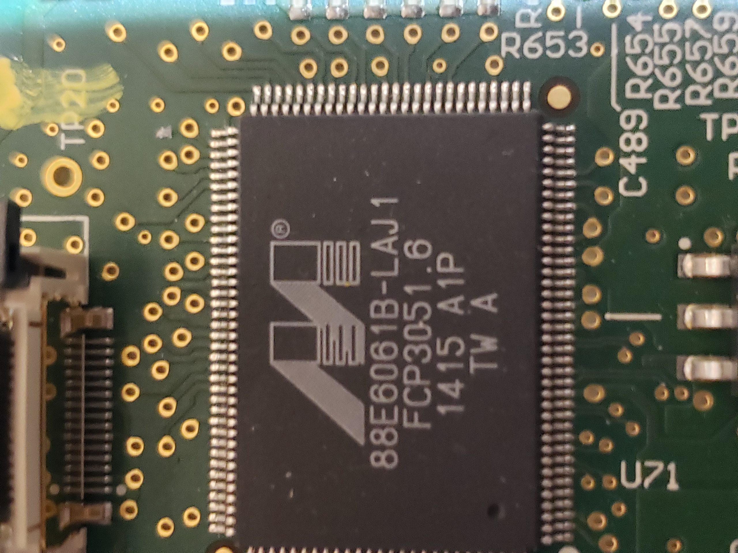
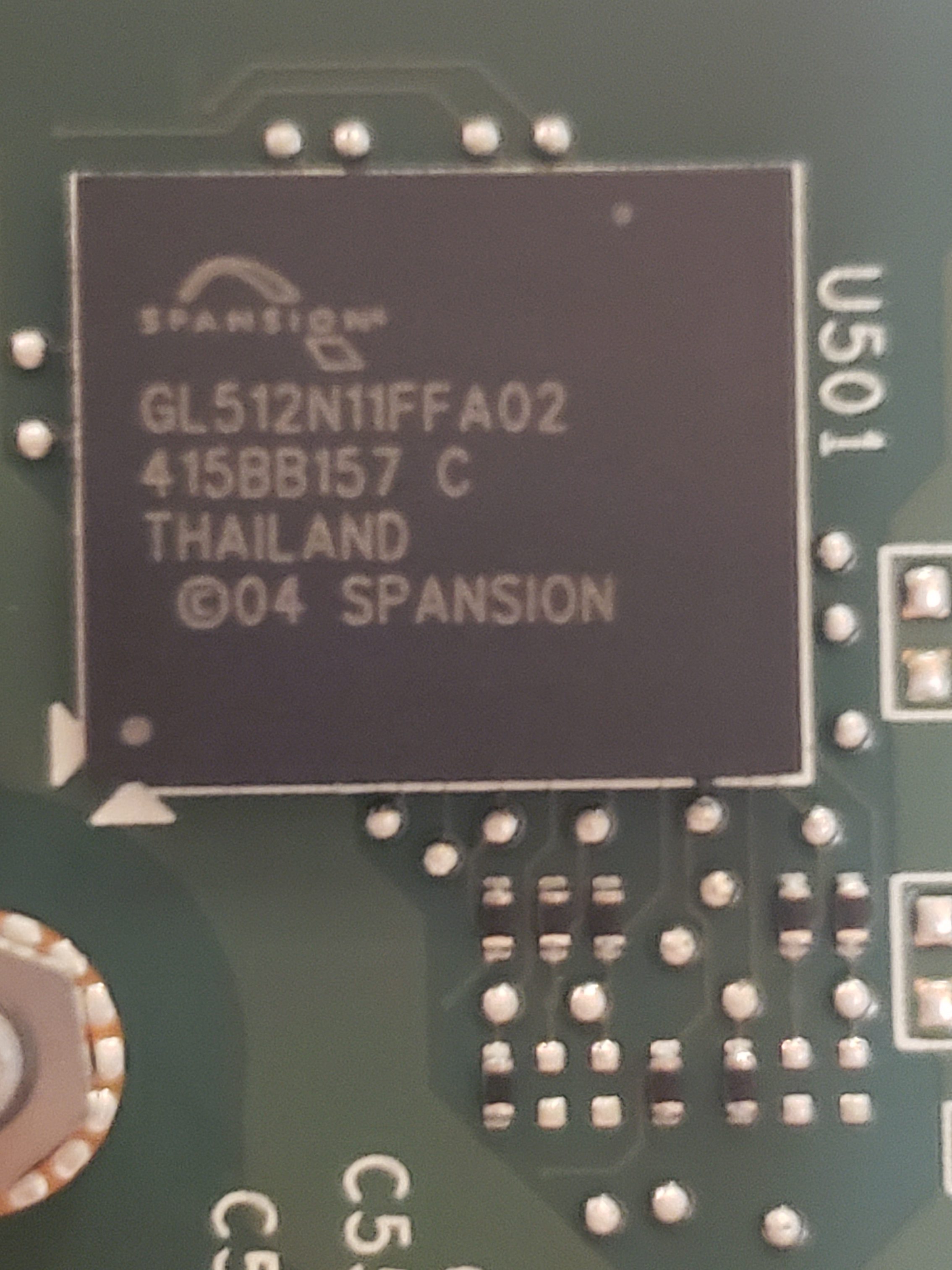
Given the size of the main board, it shouldn’t be surprising that there are many components of interest here. On this board, there are numerous communications chips: Switched gigabit Ethernet, multi-media serial links, CAN, and LIN. As I know the MCU plays “gatekeeper” for both Ethernet and CAN communications, reviewing these components for weaknesses will be a high priority.

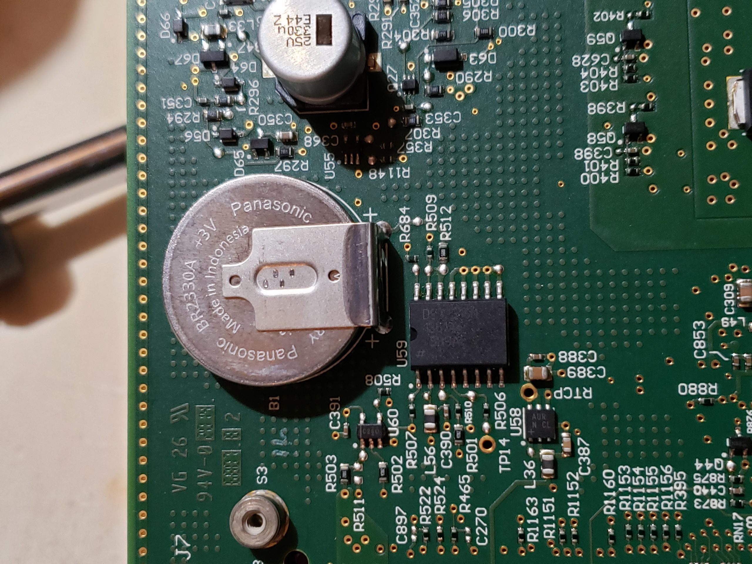
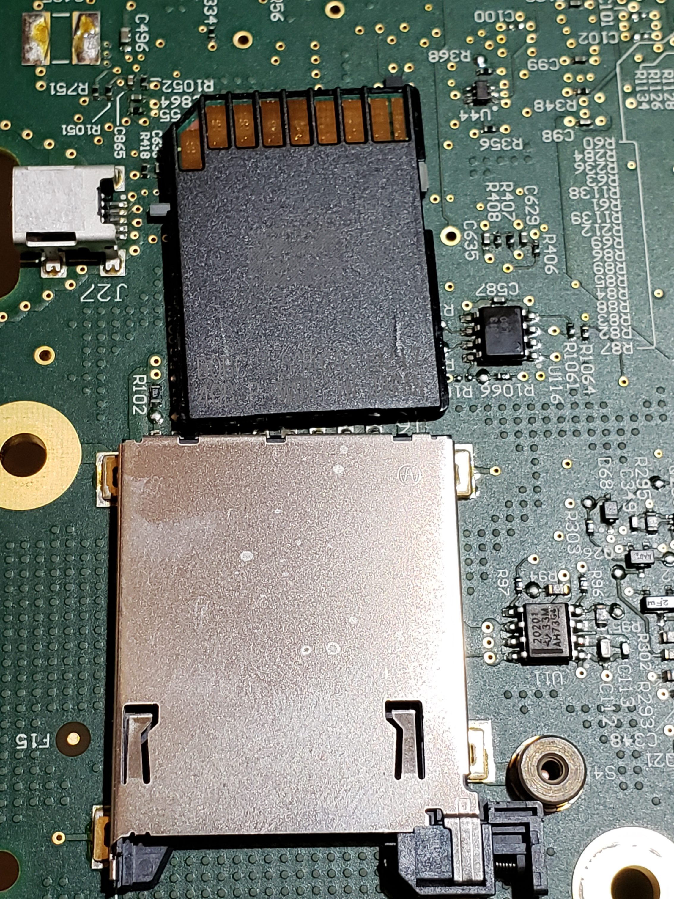
Aside from the communication ICs, this board also contains Micro SD & SD data cards, a hidden USB port, and multiple JTAG/TI diagnostic connectors. While I’m not going to “spill the beans” (yet) on the contents of the data cards, I will say there are both very useful for reverse engineering purposes. I will point out that NEITHER card is automotive/harsh environment grade. Because of this, they will fail much sooner due to the temperature extremes in a vehicle. If either of these cards fail, you are in for a very bad time!

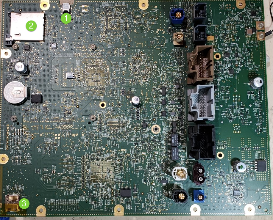
C:\Users\317FX6~1\AppData\Local\Temp\SNAGHTMLa00f8bd0.PNG

“Ports of Interest”

As noted in the sections above, there are some connection points of interest. The following tables is a consolidated list for reference.

Next Post: Navigation Repair

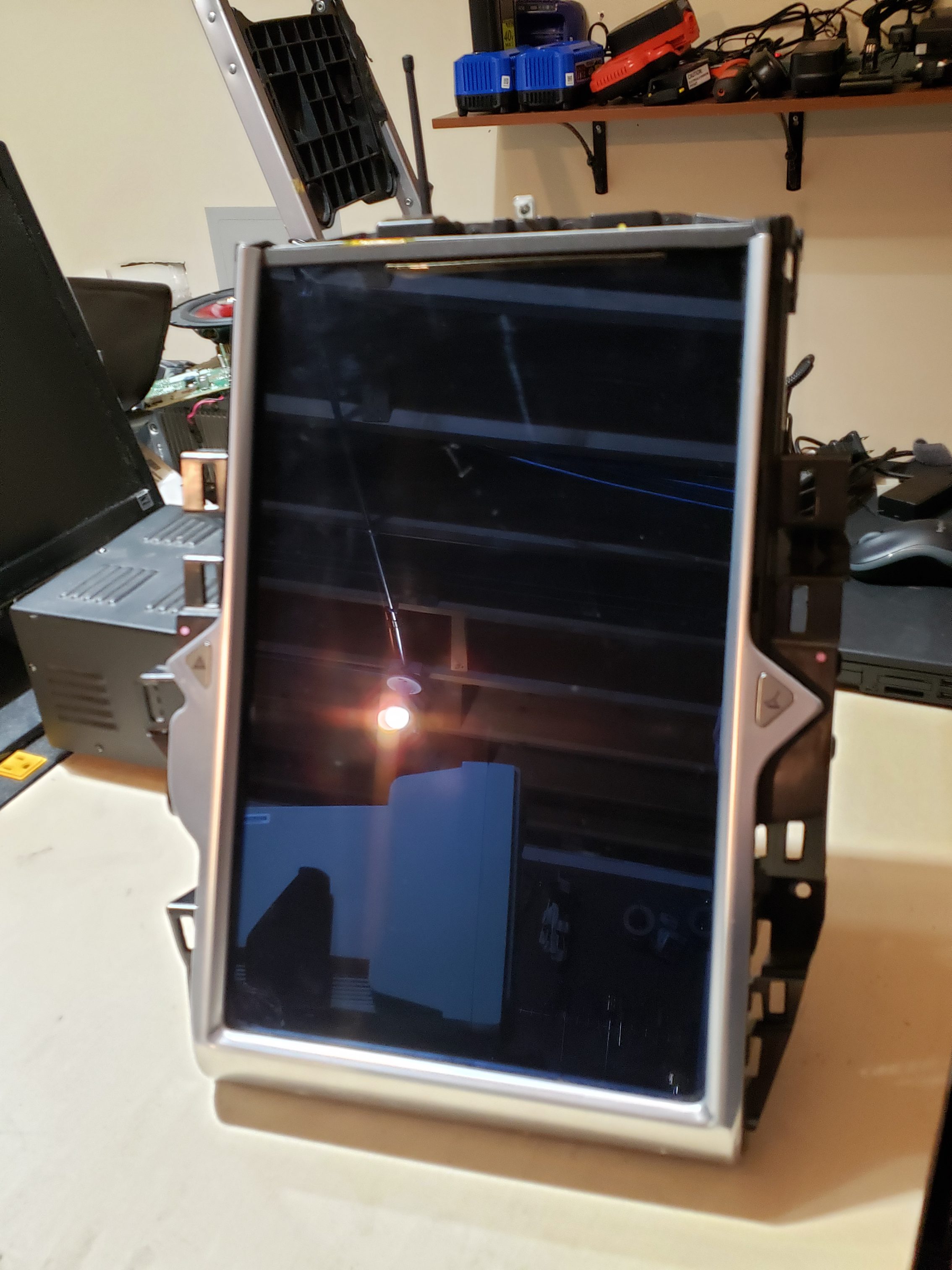
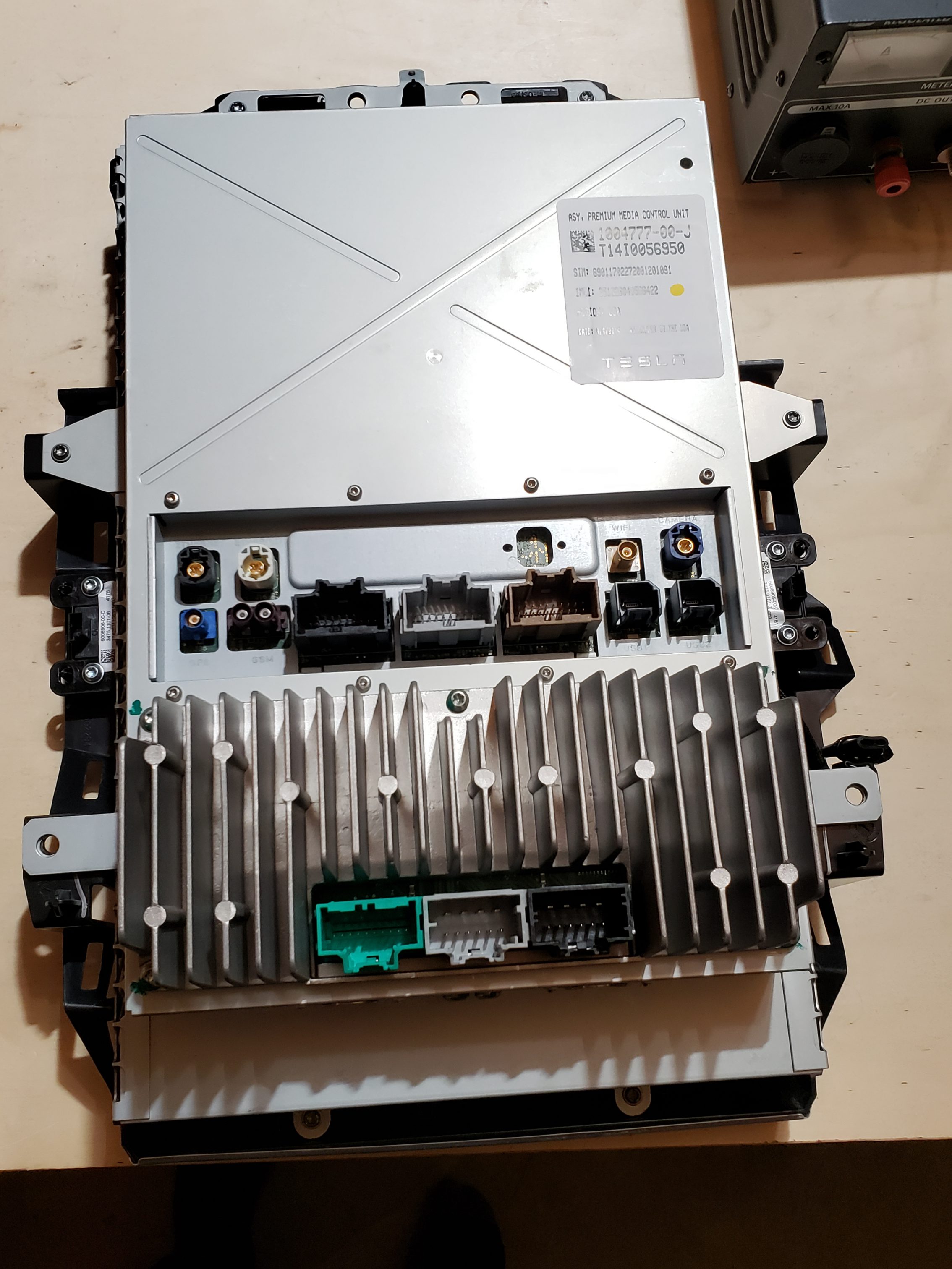
In the next installment, we’ll dig into my Navigation Issue and how the information learned during this disassembly allowed me to ultimately resolve the issue.
Security Devices, only as good as their implementation…

Security Devices, only as good as their implementation…

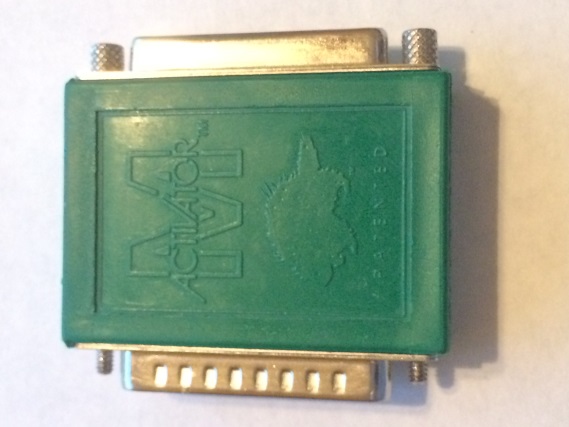
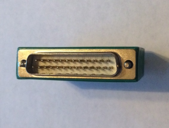
Recently, I needed to use an old program that is protected by a security device. The device, an M Activator hardware key, connects to your computer’s parallel port.

C:\Users\beyerch\AppData\Local\Microsoft\Windows\Temporary Internet Files\Content.Outlook\K9R4HEY5\IMG_9355.JPG C:\Users\beyerch\AppData\Local\Microsoft\Windows\Temporary Internet Files\Content.Outlook\K9R4HEY5\IMG_9356.JPG

Figure 1 – M Activator Security Key

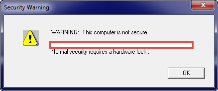
If the security device is not attached to the PC, the application program will restrict your access to certain application functions or prevent you from using an application altogether.

C:\Users\beyerch\AppData\Local\Temp\SNAGHTML1dd2ee31.PNG

Figure 2 – Application Rejection due to no hardware key

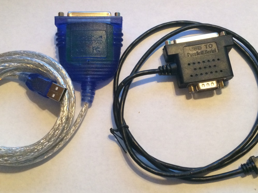
Since I own the software and still have the security key, none of this should be a problem. Unfortunately, modern computers no longer have parallel ports! As the software isn’t maintained, I can’t call the original provider for an alternative leaving me with few choices. The first, and preferred, choice was to purchase a parallel port to USB adapter on-line. I purchased two highly rated units; however, the software failed to recognize the dongle when connected through either of the units.

C:\Users\beyerch\AppData\Local\Microsoft\Windows\Temporary Internet Files\Content.Outlook\K9R4HEY5\IMG_9358.JPG

Figure 3 – Parallel to USB Adapters (that didn’t work..)

As the USB adapter routed was unsuccessful, my remaining option is to …. hack the security key or its implementation in the application program..

A Ridiculously Brief Discussion on Security/Hacking

The first rule of hacking is that you don’t talk about hacking. Wait, or is that the first rule of Fight Club? The first rule of hacking is to accept the fact that nothing will be 100% secure.

When a product is developed, the security implementation is typically driven many factors such as:

  • What is the risk/damage of being compromised?
  • How likely is it that the product will be attacked?
  • What impacts to the development process will occur due to security?
  • How will the timeline be impacted?
  • How will users of the product be impacted?
  • Does the development team understand and have security experience?
  • How much will can we afford????

Because of all of the competing considerations, product security typically looks more like the Griswold family truckster than the shiny red Ferrari.

Figure 4 – Typical Security vs Assumed Security

From the hacker’s perspective, product security really boils down to how badly they want it. Do they have the time, resources, team/skills, and money to dedicate to their mission.

In the case of my ancient dongle security application, I’m willing to invest about 60 minutes into seeing if I can get anywhere. After that, I dig out one of my older computers and use it with this program. (and hope it doesn’t ever die…..)

With that said, let’s see just how secure this old dongle application is…

Hacking 101

Now that we’ve decided that we’re going to take a stab at working around the security device, the first thing we need to do is gather information about our target. Before we can formulate a plan, we need to know what we’re up against. After about 5 minutes of research, we know the following about our target application/security device:

  • Application Program
    • Windows 32 bit executable
    • Written in C++
    • Program appears to leverage multiple external libraries, some of which are known/some are not
      • ZIP/PKZIP – File Compression
      • W32SSI.dll/.lib – ? Not sure. (yet)
  • M Activator Green Key
    • Made by Sentinel
    • The W32SSI files are related to this dongle

NOTE: Researching this scenario finds a lot of “hits” to people with similar scenarios. There are emulators and other products made to solve this problem; however, I’d rather try to figure it out myself first.

Given what has been found, it seems likely that the application program is going to use the W32SSI files to talk to the dongle. Depending on how this is done in the application, we may be able to update the application program and simply bypass the dongle. All we need to do is take a peek at the application software to see what is going on, no biggie.

Source Code, Assembly Code, Machine Code, Oh My!

If this were our application program, we could simply open it in our editor, make our desired changes to the source code, recompile the code, and be on our way. Since we didn’t write this program and the original company is no longer in existence, this isn’t an option. While we could look at the executable binary (e.g. Machine Code) unless you have a photographic memory, know low-level Windows modules by heart, and Intel OpCodes like the back of your hand, it’s going to be impossible to directly analyze the chain of files.

Figure 5 – Machine Code, no problem…..

While it might be cool to rattle off machine code instructions on trivia night, it would take us forever to try and analyze an application in this manner. Fortunately, there are many programs that we can leverage which will translate the machine code into something slightly easier to deal with, assembly code.

Figure 6 – Assembly Code

While assembly code is not nearly as friendly as actual source code, it is a 1 to 1 representation of the machine code in a somewhat human readable format. If you have an appropriate tool, such as the IDA Pro disassembler, you can convert the machine code into the assembly. This tool also allows us to map out the program flow and find text and object file references.

Using the IDA Interactive Disassembler

As mentioned previously, we can use IDA to do a quick search to see if our security device program is called. Since we know that the program uses the security key, we should be able to find one or more references to the W32SSI library files. Depending on how many and what type of references we find, we may be able to easily alter the program so that we can bypass the security hardware.

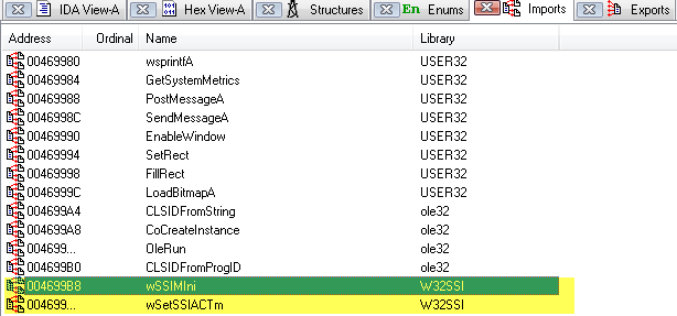
After opening the program in IDA, we can easily see that the W32SSI libraries are being used by checking the Imports section of IDA.

Figure 7- IDA Imports

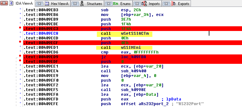
In addition to verifying the presence of the libraries via the Imports screen, we can use the Functions / IDA view to find the code references:

Figure 8 – Locating code references to W32SSI

Somewhat surprisingly, the only two functions imported from the security program are referenced once!

Figure 9 – Code section using W32SSI functions

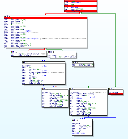
While we do not know what those routines do entirely, since they are only called once, it is safe to assume that they attempt to validate that a security key, of the right type, is connected. To help understand what we’re seeing, we can use the Graph View feature to get a visual representation of the code:

Figure 10 – Graph View of W32SSI logic

Looking at the Graph View of the code leveraging the W32SSI routines, we see that there are two main code branches. The branch on the left performs secondary checks and ultimate ends up with failure messages relating to a security key not being found. The code branch on the right simply returns a value of 1, which presumably is a “TRUE” response.

The Quick and Easy Fix

Looking at the code structure, it appears that the second W32SSI call is performing a check as to whether the security dongle is present or not. If the security dongle is found, a “TRUE” (1) is returned; otherwise, secondary tests are performed. (e.g. serial port instead of LPT, etc.)

Because of this, there appears to be a very easy way to “fix” the program. If we force the initial check to always return TRUE (or flip flop the PASS / FAIL check) then the application program will behave as if the key was present.

The following logic needs to be tweaked from:

call wSSIMIni
cmp eax, 0FFFFFFFFh
jz loc_409FBA

to:

call wSSIMIni
cmp eax, 0FFFFFFFFh
jnz loc_409FBA

JZ and JNZ are machine code instructions that are used in conjunction with comparison checks. If the result of a compare (CMP) instruction is ZERO, a Jump if Zero (JZ) instruction will result in a jump to another portion of the application. Jump if Not Zero (JNZ), on the other hand, results in a jump if the compare (CMP) instruction is non-zero.

To make the change, switch to the Hex View, right click on the highlight value and change the 84 to 85.

Figure 11 – Switching JZ to JNZ

After committing the change, you will see the code switch from

to

After starting the program, we no longer receive an error about the missing security key and the program operates as expected.

Well That Easy…..

While it may be hard to believe that changing one byte of data, by one digit, entirely bypassed an application’s security, this is a surprisingly common scenario. The security dongle used by this application could have been utilized much differently preventing this type of scenario, though. (e.g. the dongle could have stored a required piece of information that the application would need to operated properly)

HFM – Removing Years

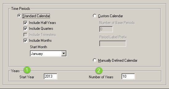
One of the most important steps during the creation of your application creation is determining how many years should exist in the application.  Specifying too many years could result in having wasted space and poor application performance while too few years could result in running out of room in your application when you hit the upper limit.

HFM Application Profile Editor (Pre-11.1.2.4 shown, though same applies to 11.1.2.4)

When HFM first shipped, you had no means of updating the Start Year or the End Year of your application; therefore, a mistake during the application creation process could lead to major headaches in the future.  As customer’s HFM applications matured and those upper year limits were getting close, Hyperion/Oracle rolled out the capability to add more years to the applications.  (with 11.1.2.4, there is a built in function to do this)

When it comes to removing years from the application, you can clear data from years; however, there is not a way to actually remove the years in the application.  Unfortunately, Oracle has never released guidance or functionality for altering the Start Year and will tell you that it isn’t possible to change this.  I’m here to tell you that, you can absolutely change this!  Before we get into how to make those updates, some quick words on why you’d want to do this and some considerations around it.

Reasons to remove years from your application:

  • Database has grown significantly due to continued use of the same application over many years
  • Metadata is cluttered due to the need to ensure historical data remains consistent
  • Prior years are no longer used for reporting  and are not necessary
  • Minimize the years displayed in the U/I to only valid years
  • Reduce the number of database objects (data tables may exist for each year/period/scenario combination)

Considerations when removing years from your application:

  • Beginning Balances for Balance Sheet accounts – (e.g. If our Start Year changes to 2015, we will still need prior year ending balances)
  • HFM Rules/Calc Mgr – (e.g. ensure that rules are not impacted by beginning year change

Process to change the Start Year:

  • “Easy Steps”
    • Make a backup.  (LCM / Database Backup / etc.)
    • Create an archive application – Consider creating an archive HFM application for the historical data.  Storing the information in a separate application gives you the ability to still view the data if needed without having to make metadata trade-offs in your day to day/primary application.  Use HFM Application Copy Utility or LCM/Application Snapshot to accomplish this.  (If you already have an archive app, you can export/import data, though Journals may be slightly annoying in this instance)
    • Update Beginning Year variables / values in the application rules / data for the new Start Year
    • Stop the HFM services
  • “Not so Easy Steps”  (explained later in more detail, don’t panic yet)
    • Connect to your HFM database via your database tool of choice  (e.g. SQL Server Management Studio, SQLPlus, etc.)
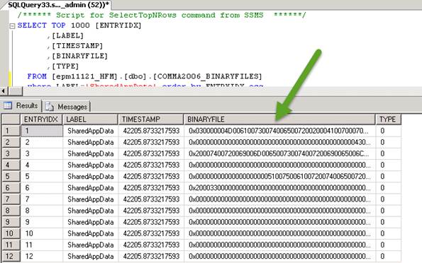
    • Query the <APP_NAME>_BINARYFILES table by ENTRYIDX for Labels of type SharedAppData
    • Update bytes 74 & 75 of the first row to reflect your new Start Year
  • Start HFM Services
  • Verify application data / functionality
  • “Post Validation Cleanup”
    • Stop HFM Services
    • Remove Year / Period specific database tables (e.g. <APP_NAME>_DCE_<PeriodNum>_<Year> )

HFM Binary Files Table

For each HFM application, you will find a Binary Files table in the format <APP_NAME>_BINARYFILES.  This table is used for multiple purposes, including storing application configuration information, application metadata, HFM rules, memberlists, etc.  The LABEL column defines the type of file the data is related to.  The BINARYFILE column contains the raw information from the corresponding file.  (e.g. Application Profile .PER file, Rules .RUL file, Metadata, etc.)  Since this column has a character limit that is smaller than most of these files, you will find multiple rows for each file type.  The ENTRYIDX column is used to order the rows in the proper order.  (Ascending order)

As the Start and End years are defined in the profile, we only want to view rows containing a LABEL of SharedAppData:

SELECT
 ENTRYIDX, LABEL, BINARYFILE
FROM
 <APP_NAME>_BINARYFILES
WHERE
 LABEL = 'SharedAppData'
ORDER BY
 ENTRYIDX ASC


SharedAppData 

SharedAppData ENTRYIDX 1 as viewed in a Hex Editor

As mentioned above, the SharedAppData rows correspond to the application profile (.PER) that defines the HFM application.  Analysis of this data indicates that both the Start and End years are stored in the first row of this information.  The Start Year is stored in bytes 74 and 75 while, the End Year is stored in bytes 78 and 79.  The data is stored in Least Significant Byte Order.  (e.g. Byte 75 is first half of year, 74 is the second)

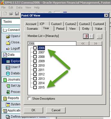
In the Shared App Data above, the Start Year is 2006 while the End Year is 2015.

Start Year (Hexadecimal) = D6 07 = 07 D6 (flipped) = 2006 (decimal)
End Year (Hexadecimal) = DF 07 = 07 DF (flipped) = 2015 (decimal)

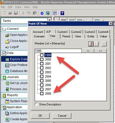
To change the Start Year, convert the decimal year to hexadecimal and then reverse the byte order.  For instance, if your new start year is 1999, you would end up with:  1999 (dec) = 07CF = CE 07

HINT:  You can use Windows built-in Calculator program in Programmer mode to make these conversions.

Update SharedAppData

After you’ve calculated your new Start Year value, create an Update query to alter the stored binary data

UPDATE query to alter Start Year


Verify Results

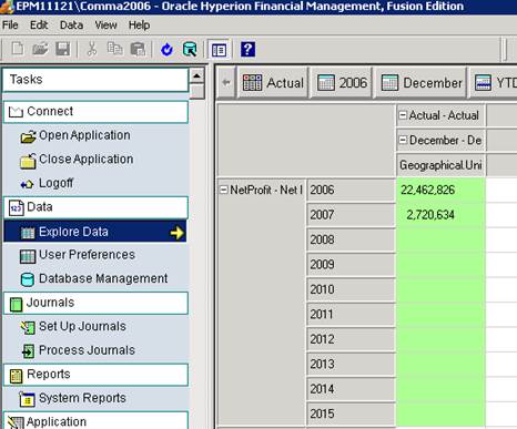
After you have updated your settings and restarted HFM, you can verify that you now have the appropriate years

Original Years


Updated Years

NOTE – While the screen shots are from an HFM 11.1.2.1 application, this has been tested through 11.1.2.4, though I won’t guarantee this works with every patch version, etc.  Always test in a non-production environment.