Overview
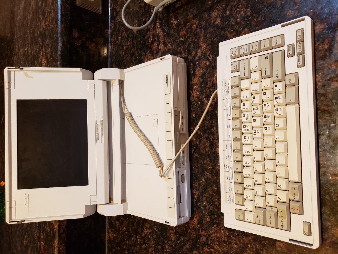
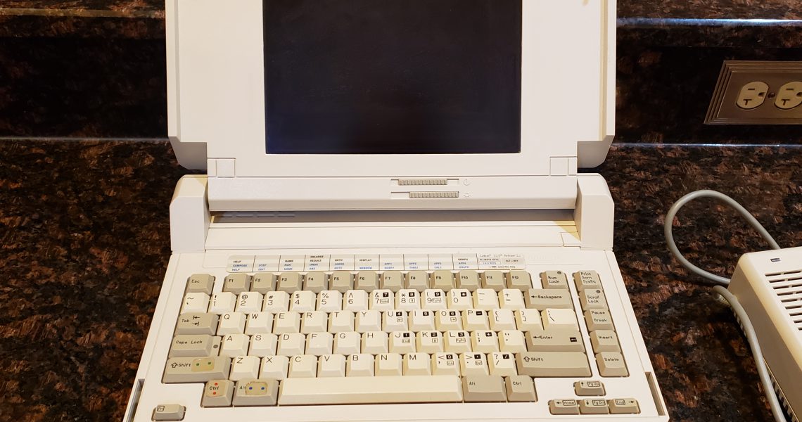
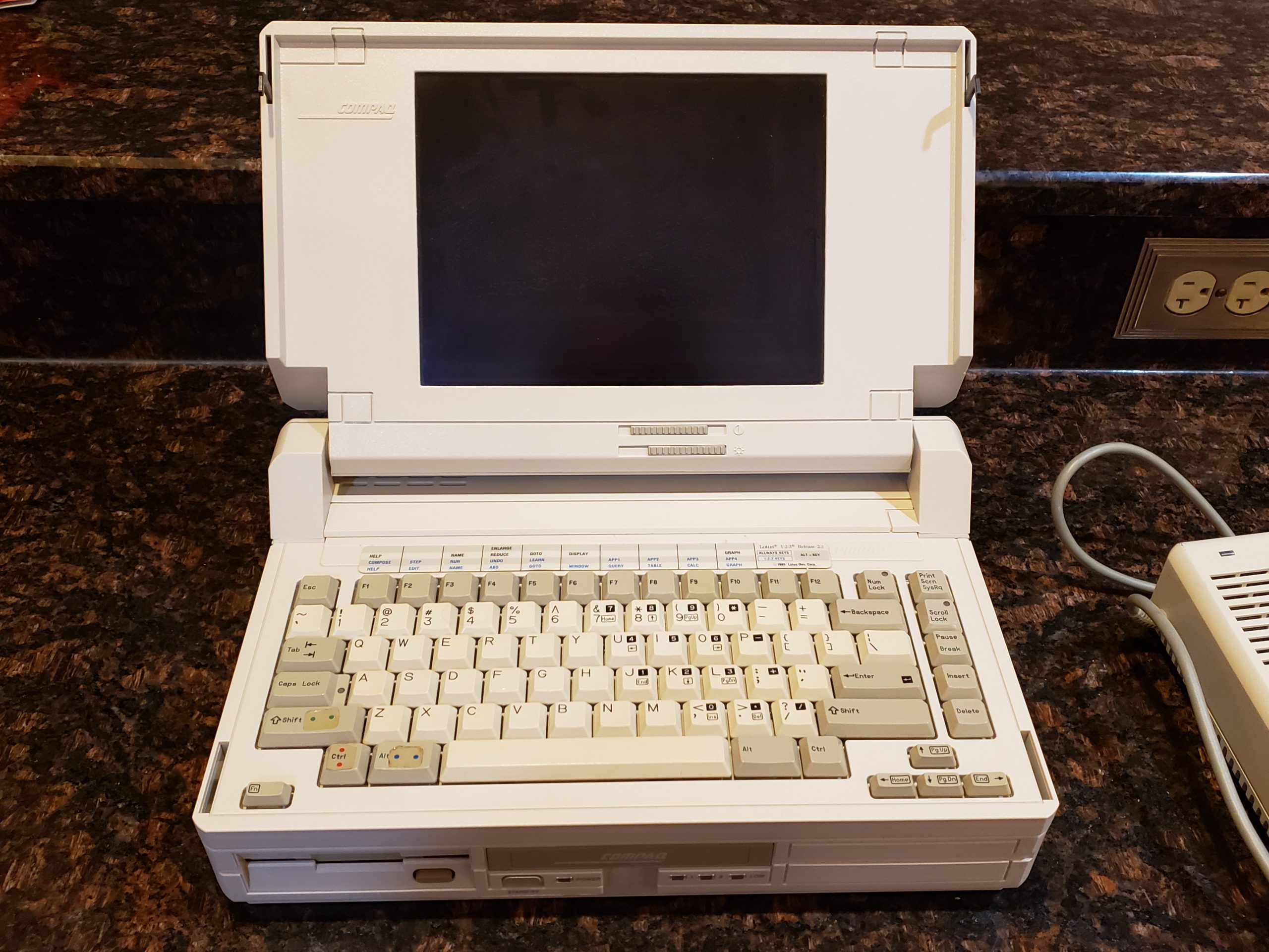
Recently, I ran across someone looking to sell an “ancient” laptop that had been long forgotten in their closet for ~30 years. The laptop in question is a Compaq SLT/286. As I’m a sucker for very clean old tech, this was right up my alley! Since it was a Compaq machine, I was especially interested as I have a few of their previous ‘portable’ machines as well.
When I inquired about the machine, the owner state that it turns on perfectly fine; however, they were not able to do much else since it doesn’t ‘boot up’. The person stated that it was a work machine that was upgraded and prompt left, in its original bag, in their closet and was only recently discovered.
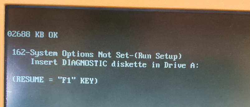
When I plugged in the machine, it did start up immediately; however, I was presented with a very familiar error message:
Issue
This error message is a clear indicator that the machine had “forgotten” certain configuration settings. In older computers, these Basic Input / Output Services (BIOS) settings are stored in a Complementary Metal-Oxide-Semiconductor. (aka CMOS) The CMOS requires a small amount of power to retain its memory. The earliest PCs typically had a small battery attached to the motherboard which would provide this power. Unfortunately, batteries do not last forever and will fail. In a best case scenario, the battery simply fails to produce enough power while in worst case scenarios, the battery loses integrity and acid can damage the motherboard.
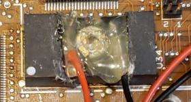
Worst Case Example: Compaq Portable II w/ catastrophically failed battery
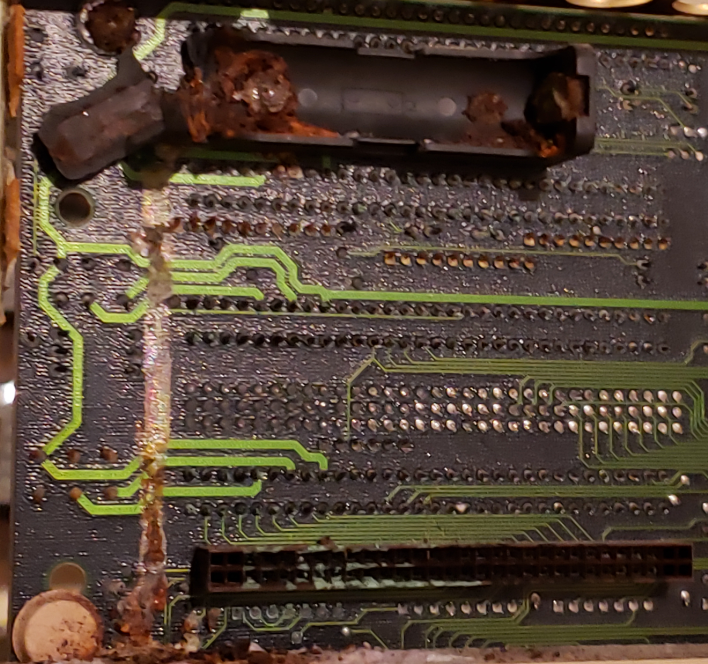
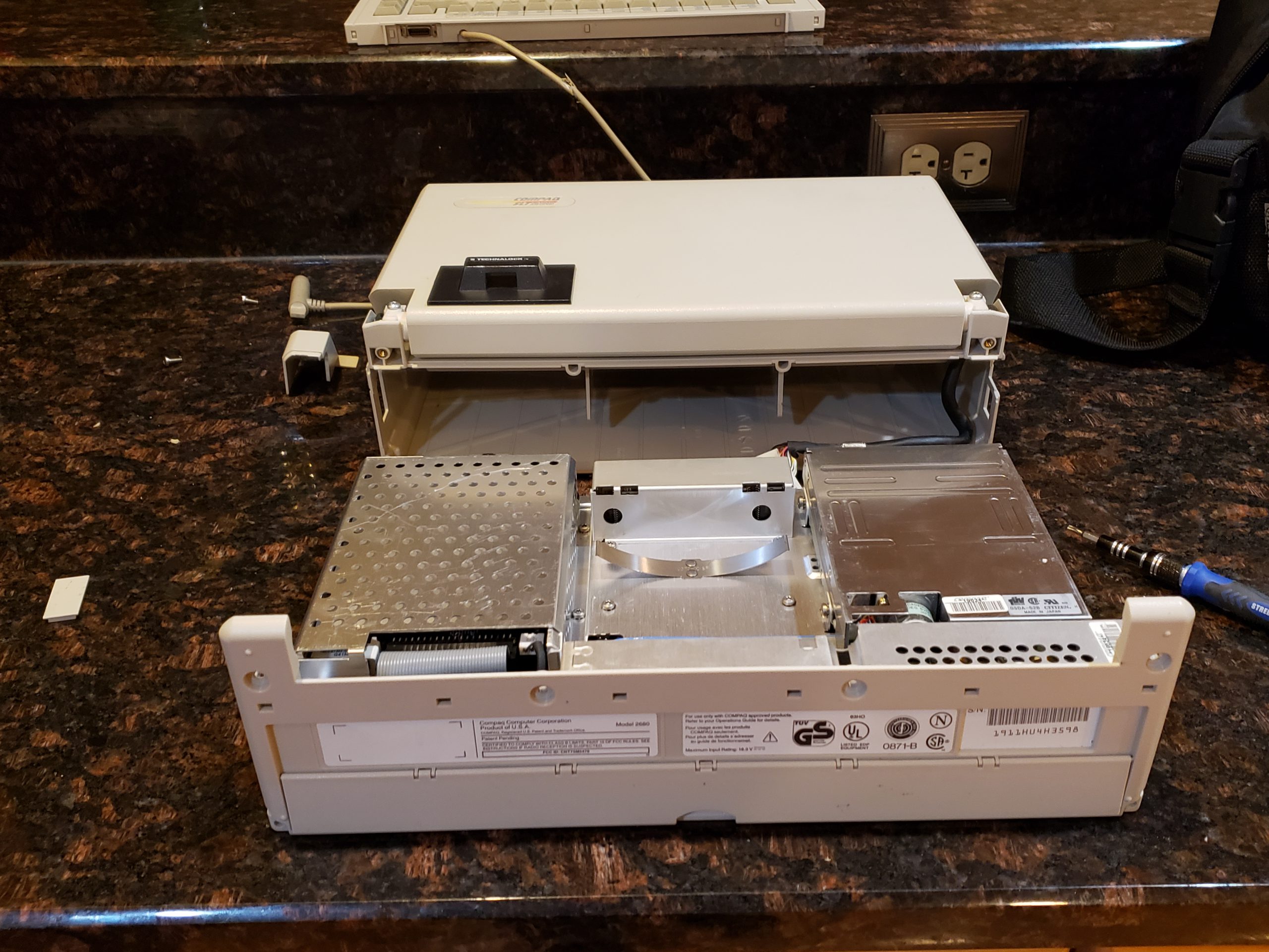
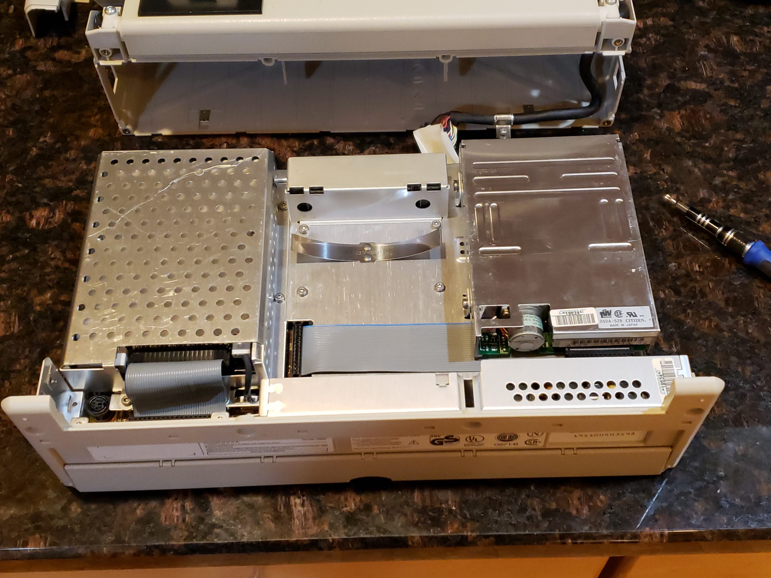
Fortunately, this Compaq model did not use a battery that could fail in such a manner and the motherboard was clean as a whistle. (see all the disassembly pics at the end to see just how clean this machine is!)
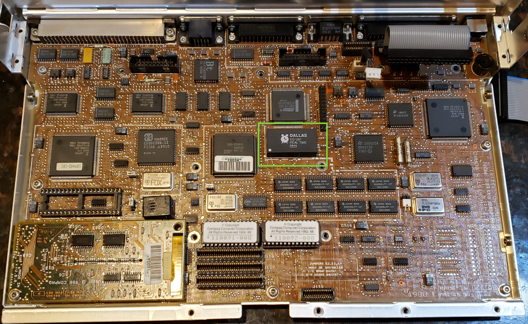
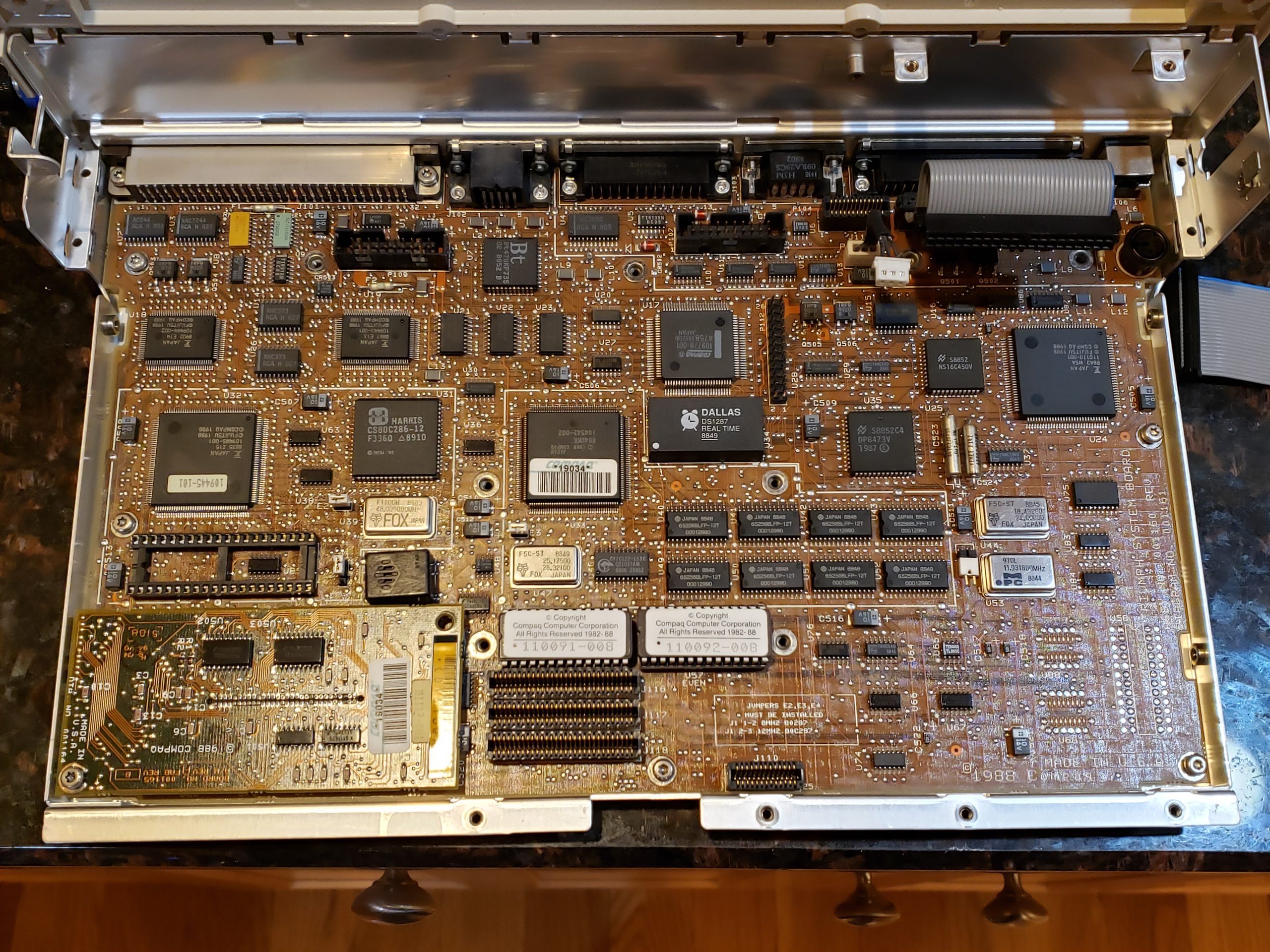
A quick scan of the motherboard also reveals that there isn’t a battery per se. For this computer, Compaq chose to use a Dallas Real Time Chip (RTC) module which stores the relevant information. This device, which is still used to this day in certain applications, performs multiple activities: “nonvolatile” RAM memory, supports certain Read Only Memory (ROM) operations, and Real-Time Clock (RTC) operations. The one “gotcha” to this device is that the RAM is non-volatile only because there is a battery hidden inside the module which provides power to the device. Once this internal battery is depleted, it is no longer a nonvolatile RAM device.

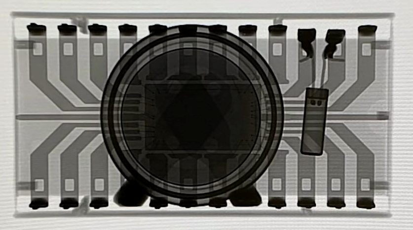
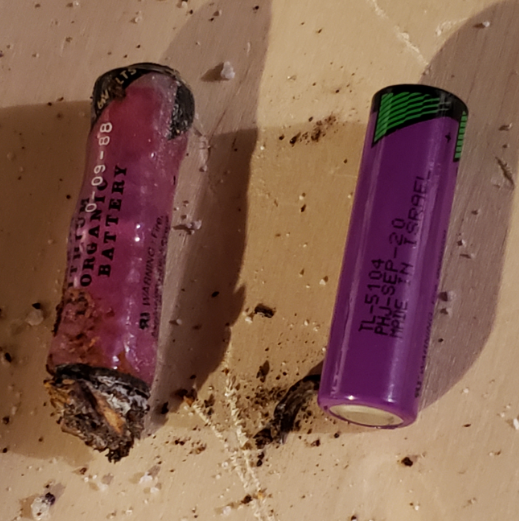
The image on the left is the module found on this Compaq’s motherboard. The ‘8849’ is the build date for the module which corresponds to the 49th week of 1988! The image on the right is an X-Ray of this type of module. The power source is the circular item near the middle of the module. (X-Ray image courtesy of https://ardent-tool.com/)
CMOS Repair
In order to get this PC up and running, we will need to address this failed module. There are a few options:
- Replace the Dallas RTC module with a newer one
- Carefully modify the existing Dallas module to power it from an external source
As with any repair, there are always trade-offs to consider. In this scenario, I chose to supply external power to the existing module for the following reasons:
- The existing module is directly soldered to the motherboard. This would require me to desolder the existing module and then solder a new one to the board. While this is not overly difficult, it requires a bit more effort and care than the other option. (If Compaq had placed the module in a socket, I would have opted to replace the module)
- Many suppliers of compatible Dallas RTC modules are selling “New Old Stock” (NOS) components. Because of this, the batteries may only last for a few years before requiring replacement again.
- Accessing the module requires a complete disassembly of the unit. (disassembly pictures are in a later section)
- If I’m going to have to replace a battery again, I’m strongly prefer to *NOT* have to disassemble the unit
- NOTE: As you’ll see later, my repair allows for a 60 second battery replacement and requires no tools.
- This approach is relatively low risk. If I make a mistake accessing the internal battery, I can always resort to replacing the module. If someone else acquires this machine and would rather replace the module, they can still do this.
The following steps were performed to implement the external battery solution:
- Carefully remove the top layers of the Dallas module’s epoxy to expose the battery
- Disconnect the battery from the module pins
- Solder new leads to the power pins
- Route wires to a convenient location
- Solder coin battery holder to other end of leads, add battery, and verify power
Module Modification
If you’ve read this far, you are probably wondering: “Why did Charles mention he used a steak knife to effect this repair”? If so, you don’t have to look any further! To cut into the module, I choose to use a nice and sharp steak knife! While a Dremel would have been more surgical, it was in the garage and I didn’t feel like trekking into the cold to fetch it. As the epoxy/resin material is relatively soft, I had no trouble using a knife to accomplish this task. Once the battery was exposed, a small wire cutter was used to disconnect the existing battery. Next I prepped some wires, soldered them to the appropriate pin outs, and sealed it with my glue gun. (Yes, I could definitely have made this cleaned, but I wanted to make sure it was working first…)

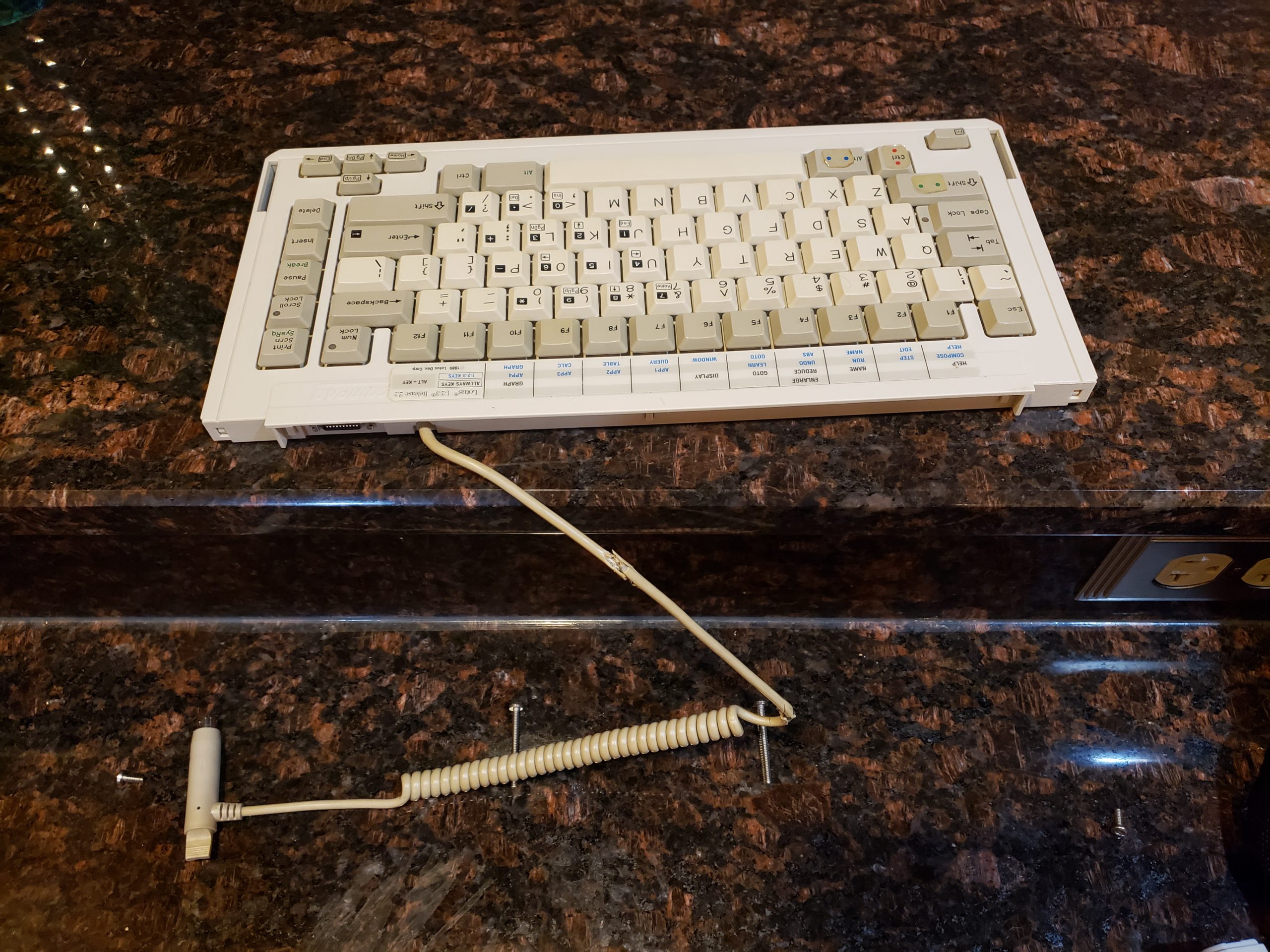
Wire Routing & External Battery
I gave myself plenty of extra wire so that I could route it to a spot where it wouldn’t impact the operation of the laptop *and* it could be easily accessible.
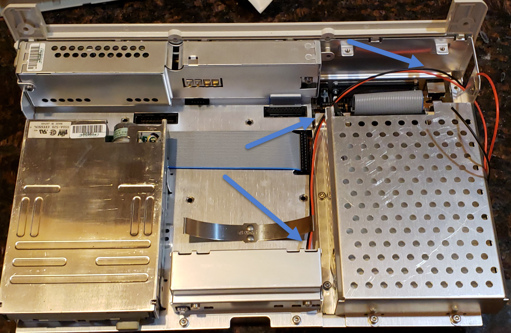
(Look how clean this unit is! Amazing)
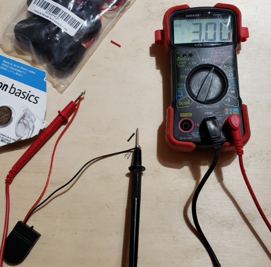
I then put together the coin battery holder and verified that I was getting proper voltage.
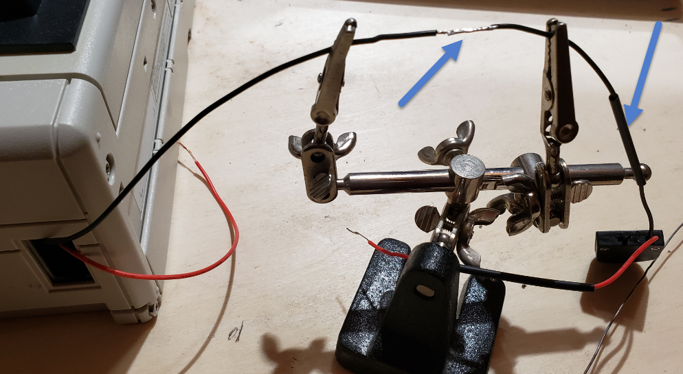
Next, I soldered the coin battery holder to the module wires. (Always use heatshrink!)
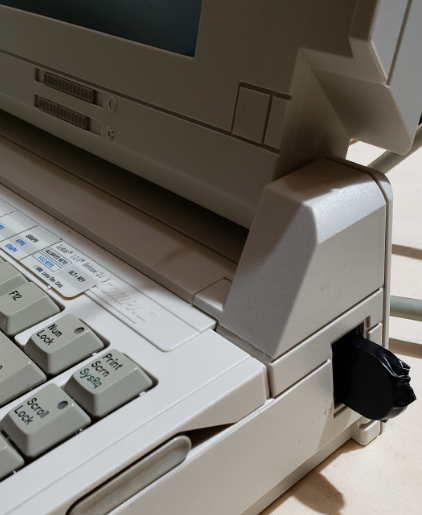
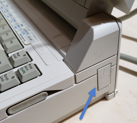
Finally, I wrapped the holder in electrical tape and tucked this into the access port on the side of the laptop. This convenient location will allow a battery swap in seconds without the need for any tools. If I add the optional model, I will need to relocate this; however, it is a perfect location for now.
With the machine physically repaired, the only thing left to do is create the Compaq Diagnostic Disk and reconfigure the device.
Software Reconfiguration
After scouring the internet, I was able to locate the appropriate software and used it in yet another retro machine to create the necessary software:
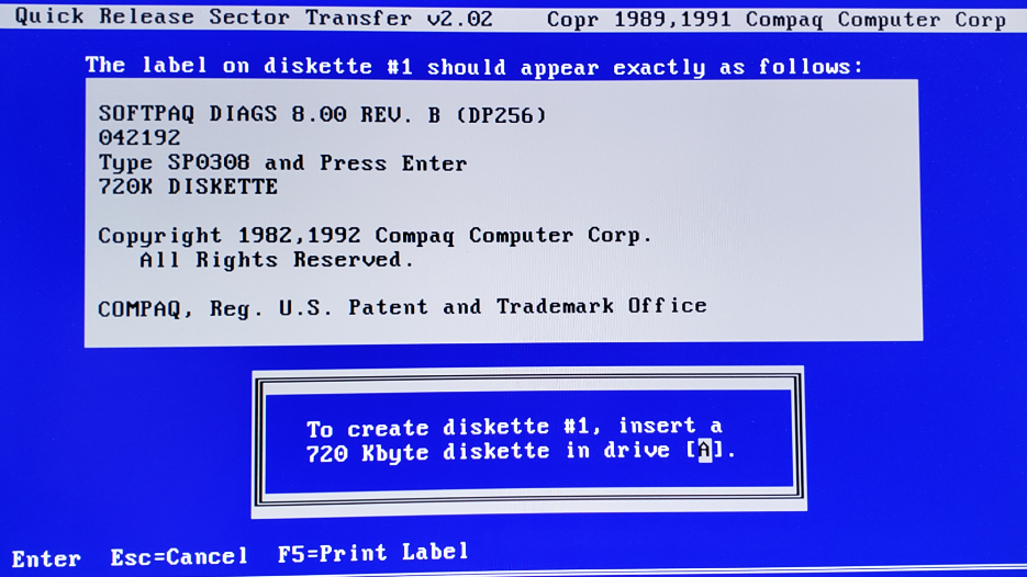
I insert this newly created disk into the Compaq, turned it on, and the configuration utility started. The utility seemingly auto-detected everything auto-magically.
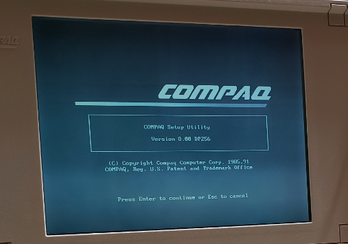
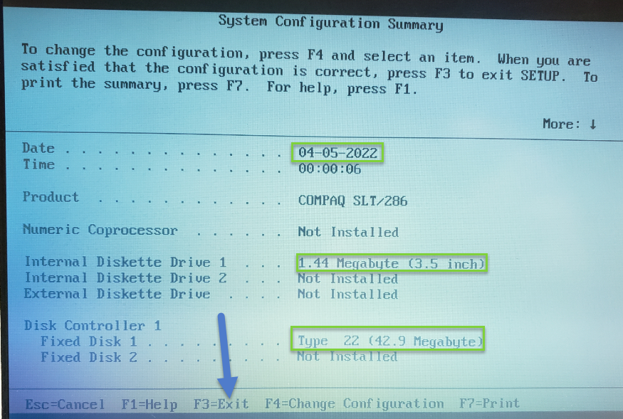
After saving the configuration, the machine started up w/o any error messages!
It Lives!
After exiting the configuration utility, the computer sprang to life and I was greeted with a DOS prompt. Looking around on this machine, I found some pretty standard late 1980’s business programs. Quite a trip down memory lane.
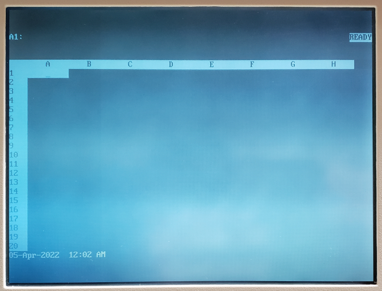
1-2-3
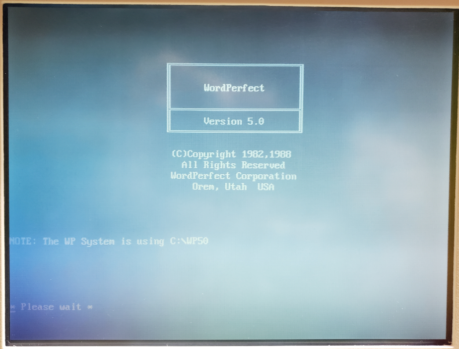
WordPerfect
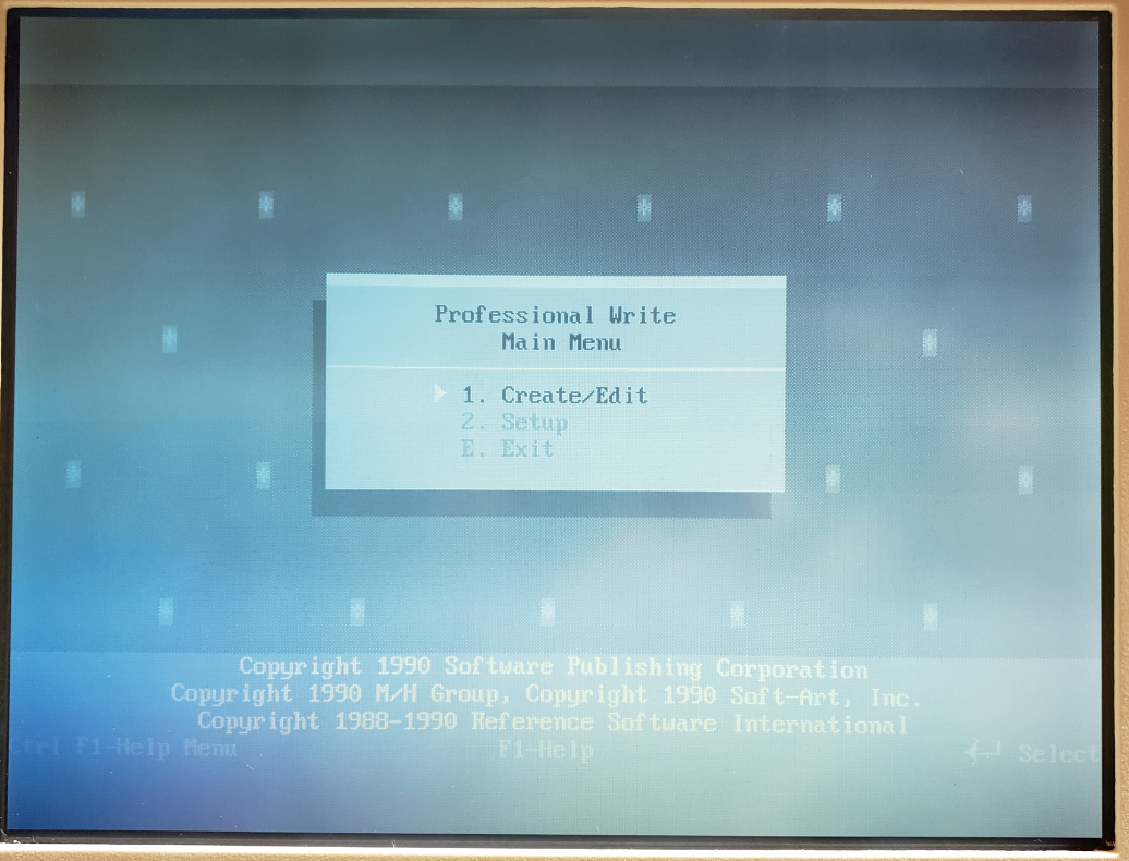
PFS Write
Bonus Pics
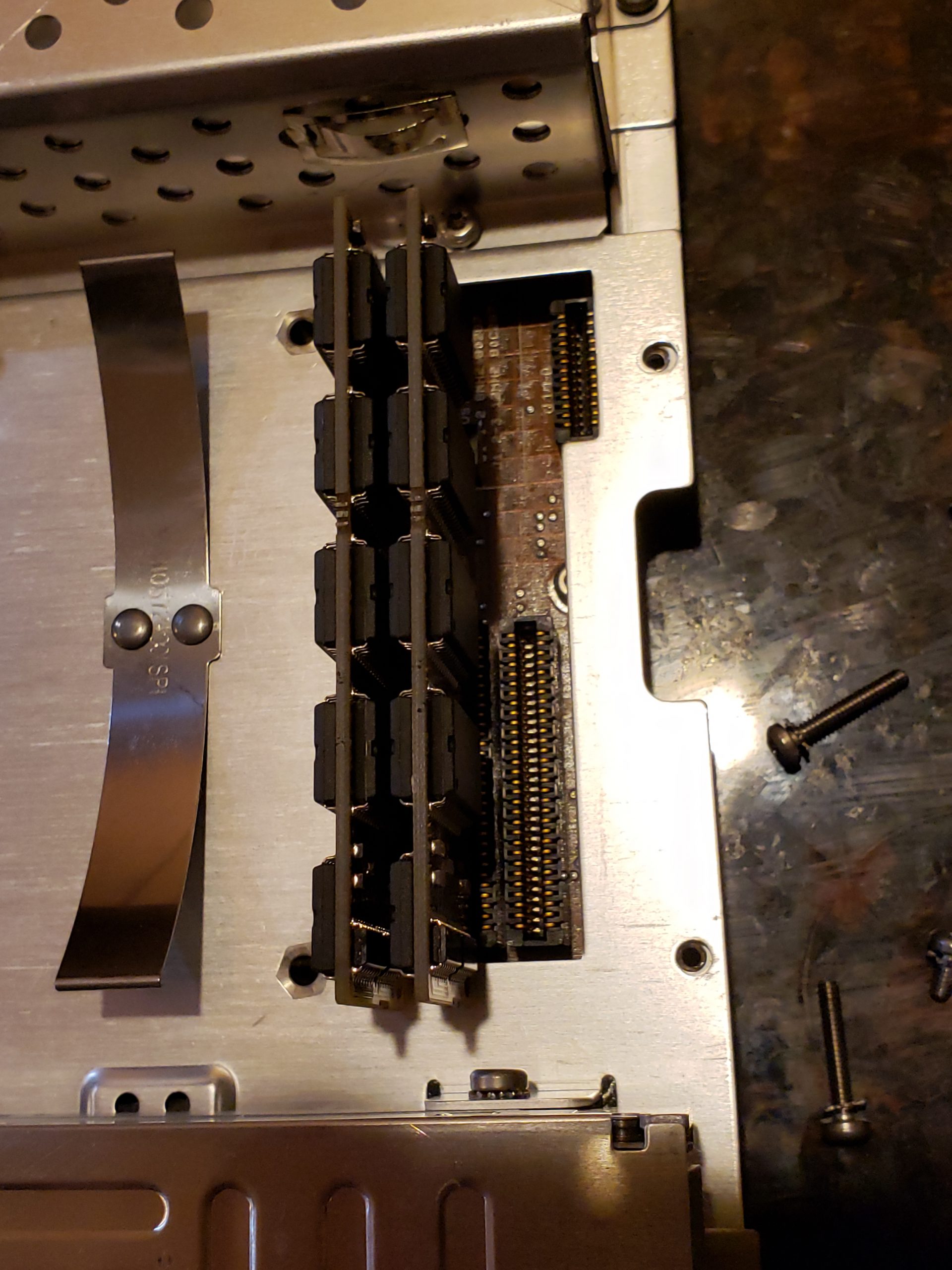
Below are disassembly and other pictures that didn’t make the cut up above. Take a look at how clean this machine is. Amazing for the age. Also, if you made it this far, there is a hint for my next post. Something else running on that workbench is a bit out of place….. If you recognize it, feel free to point it out and take a guess what we’ll be doing with it!
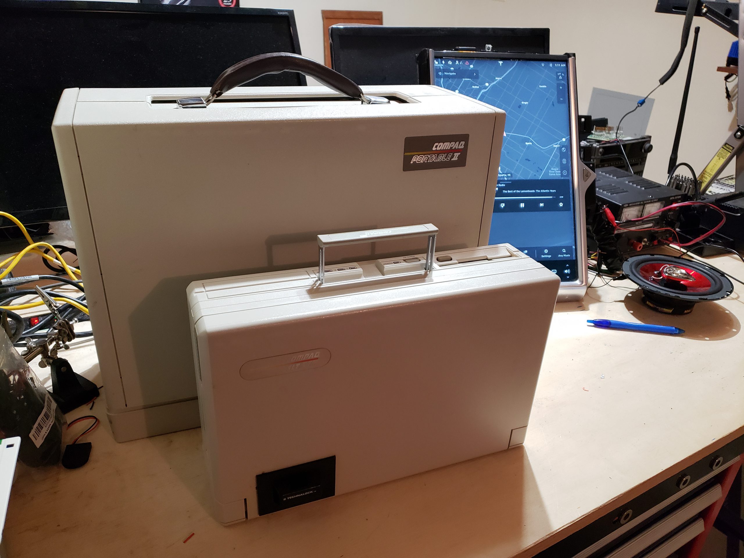
Compaq Portable Family
The largest machine is only a couple years old. Amazing at how much they shrunk down the electronics! Another post is going to dig into that machine and you will be able to see the difference!
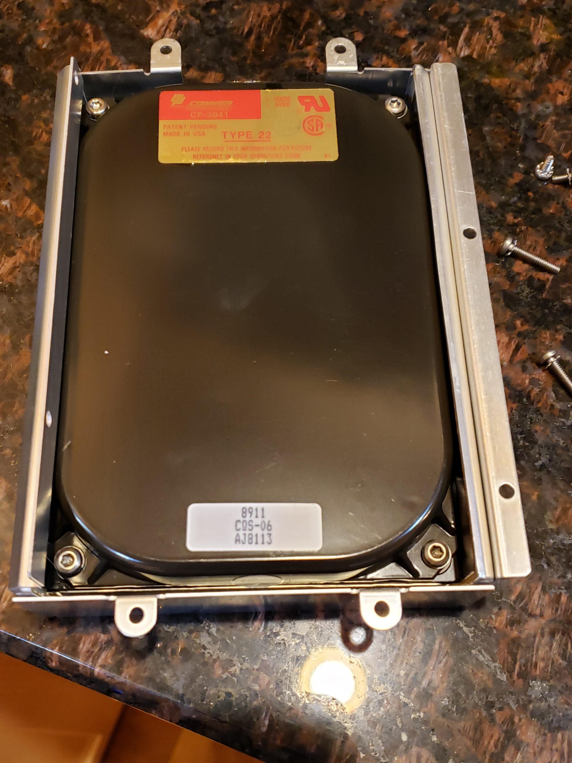
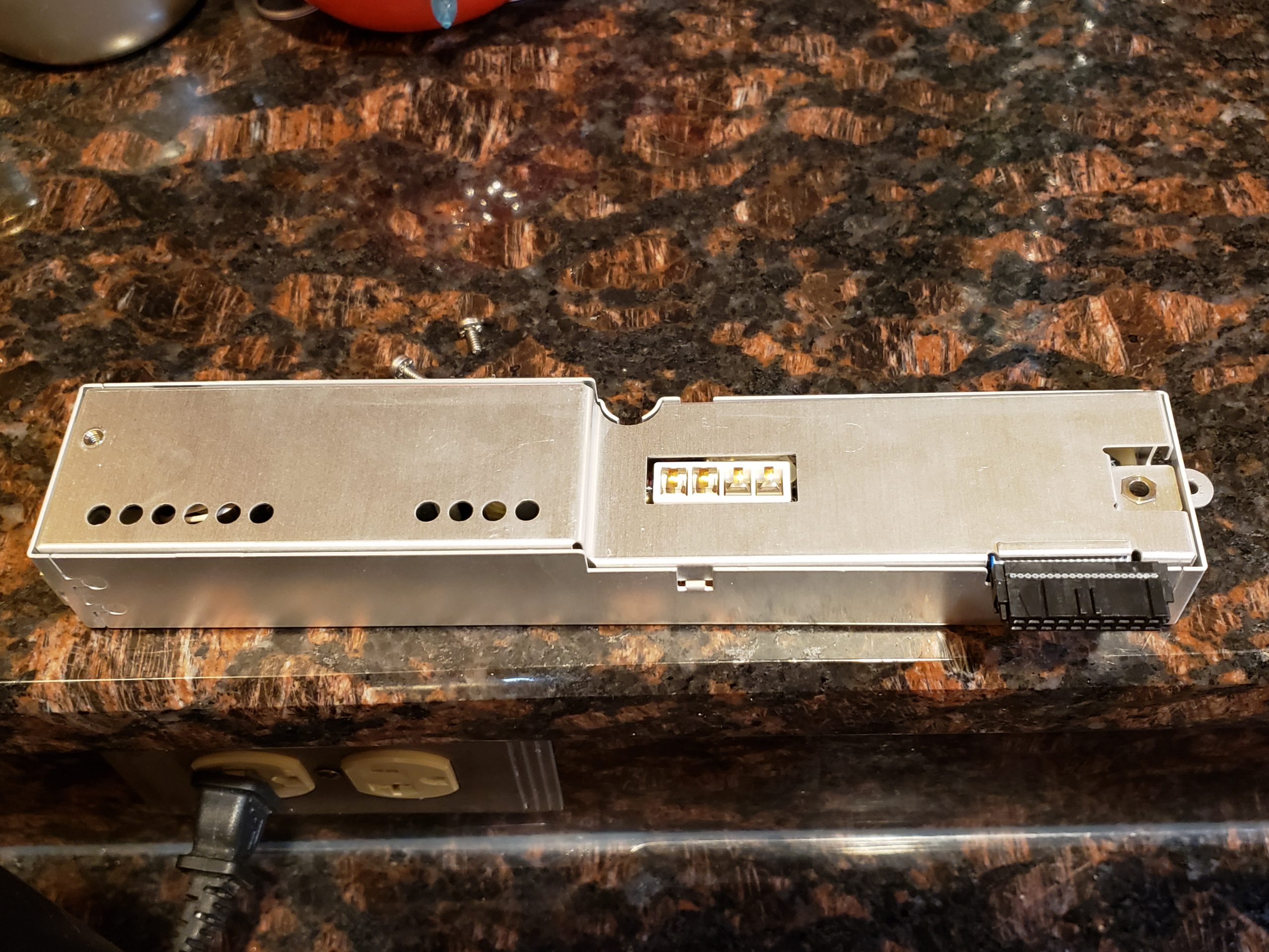
Disassembly